Cortical visual prosthesis

a visual prosthesis and cortical technology, applied in the field of cortical visual prosthesis, can solve the problems of diabetic retinopathy, vision loss, blindness currently incurable,

Active Publication Date: 2016-04-05
CORTIGENT INC
View PDF12 Cites 3 Cited by
  • Summary
  • Abstract
  • Description
  • Claims
  • Application Information

AI Technical Summary

Problems solved by technology

Many leading causes of blindness are currently incurable—and once the damage is done, patients with vision loss from diabetic retinopathy, glaucoma, or trauma to the eyes or optic nerve currently have no hope of recovering vision.
Treatment options for most types of age-related macular degeneration (AMD), the leading cause of vision loss in older Americans, are limited.
But patients with severe vision loss from AMD are often without hope of any vision recovery.
However, it can only treat patients with damage to the photoreceptors of the retina—the rest of the optic pathway must be intact.
These experiments only lasted 2-3 months, likely because the effectiveness of microelectrode stimulation degraded due to scar tissue formation and electrode degeneration.
While providing lower thresholds for shorter term experiments, the lack of long-term stability of penetrating microelectrodes for stimulation likely makes them unsuitable for use in an implant for humans.
Their more invasive design also increases the risk of adverse events compared with surface stimulation.
Because of these brain structures' relative inaccessibility and compact structure, however, achieving useful vision from such prostheses is difficult.

Method used


Image

  • Cortical visual prosthesis
  • Cortical visual prosthesis
  • Cortical visual prosthesis

Examples


Embodiment Construction

[0032]The following description is of the best mode presently contemplated for carrying out the invention. This description is not to be taken in a limiting sense, but is made merely for the purpose of describing the general principles of the invention. The scope of the invention should be determined with reference to the claims.

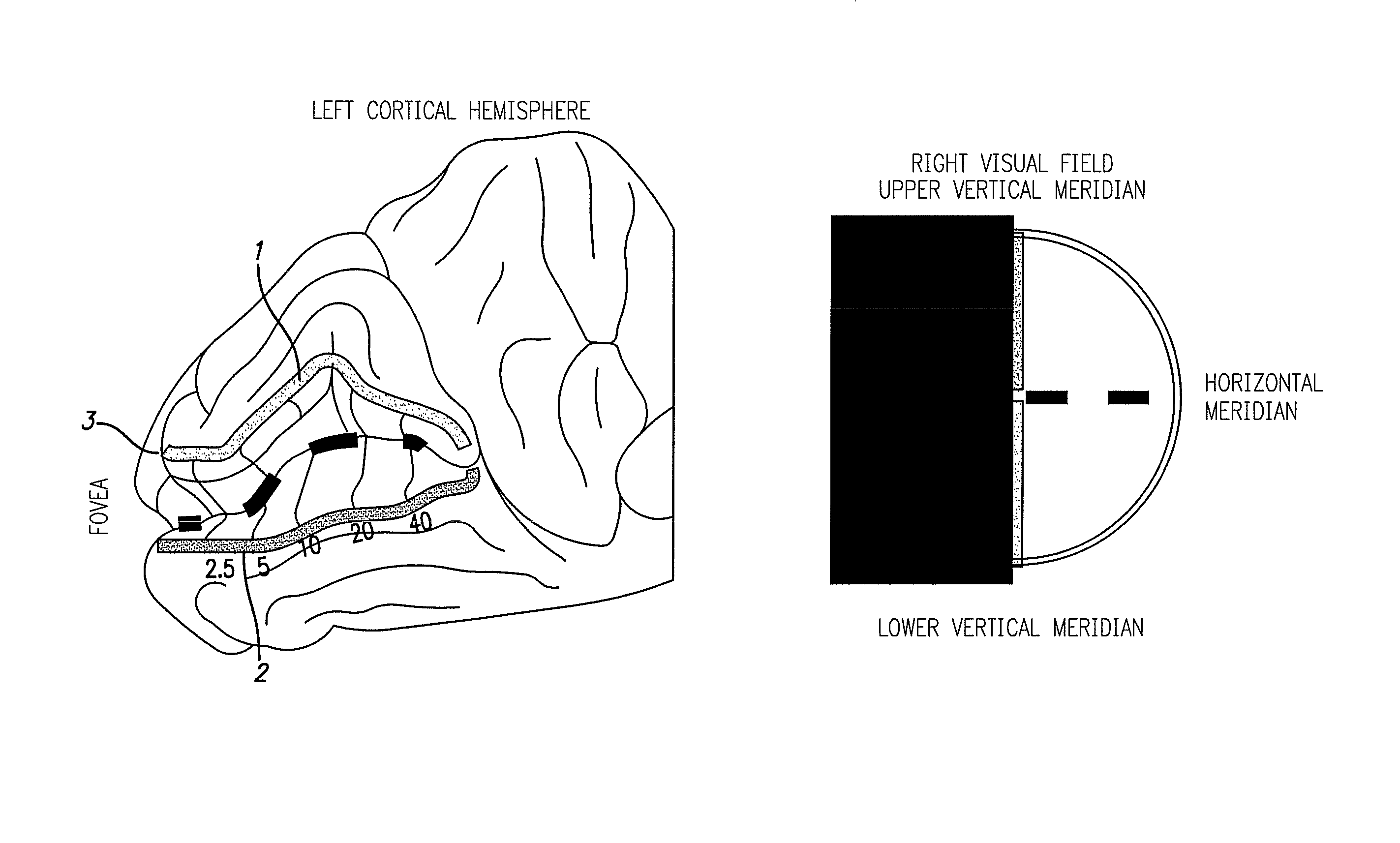
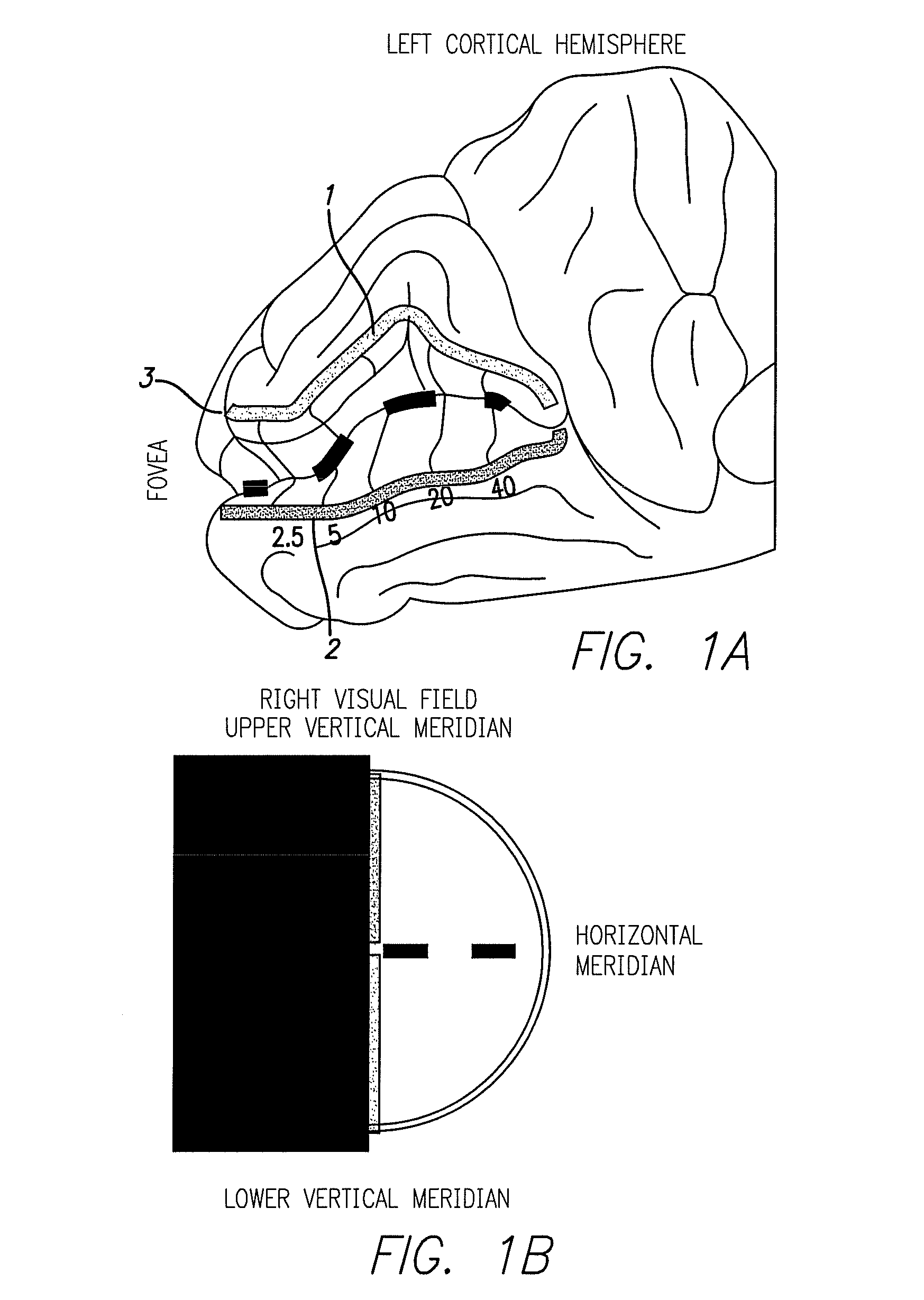
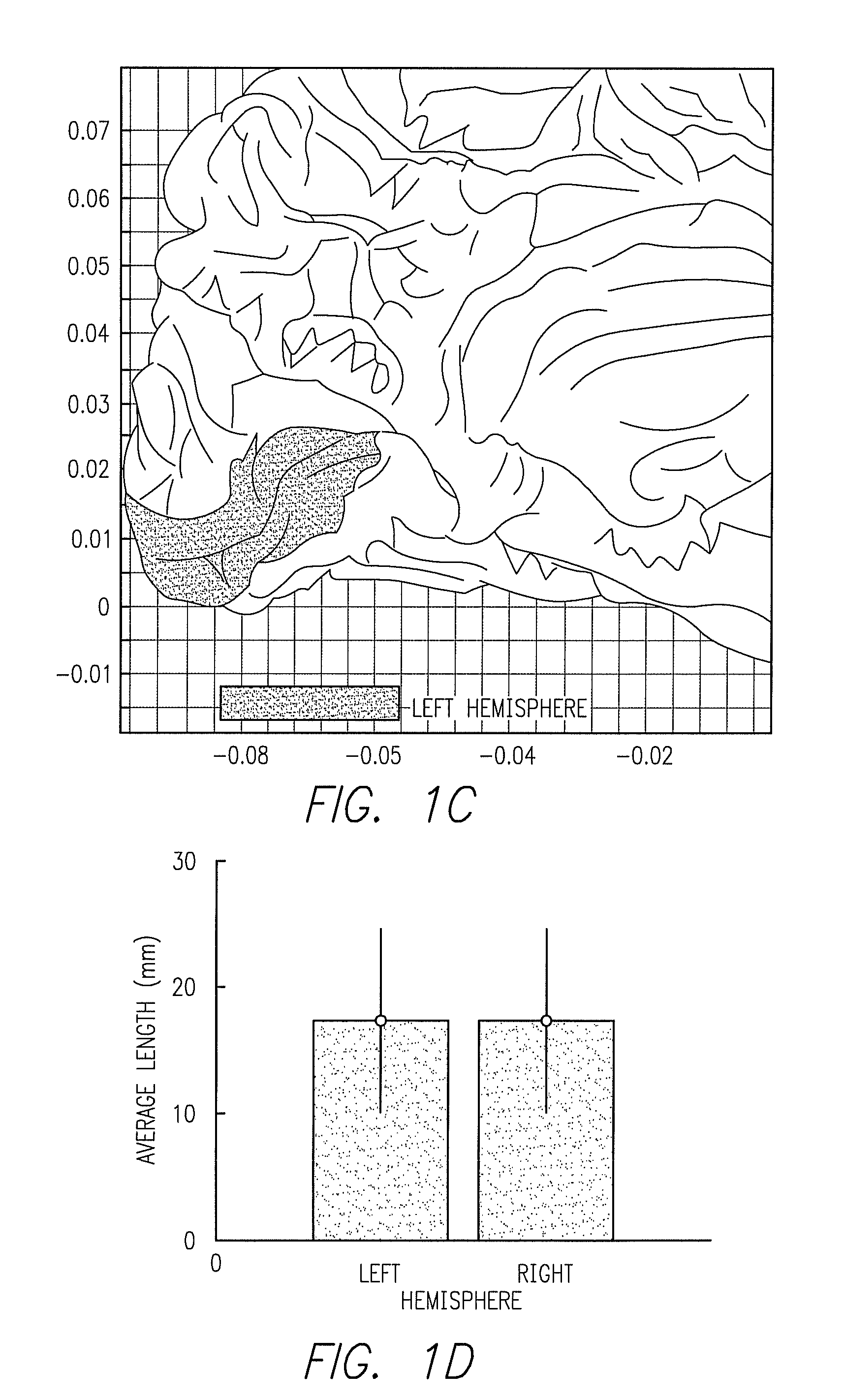
[0033]FIG. 1A, shows the left side of the back of a human brain as seen from the medial longitudinal fissure. It is opened up for visibility. The fovea 4 in the back of the head maps out the central visual field. Mappings of the Lower vertical meridian 1, Upper vertical meridian 2 and Horizontal meridian 3 (dashed), of the right visual field shown in FIG. 1B. FIG. 1C is an example of V1 in left hemisphere of a subject. FIG. 1D is the average length of the left and right calcarine sulcus for 63 subjects. FIG. 1E is a Histogram of the number of length measurements for all subjects left and right.

[0034]Referring to FIG. 2, a polymer-based flexible circuit inclu...


PUM


Abstract

The present invention is a visual prosthesis adapted for implantation in the brain, and more particularly with an electrode array adapted for implantation in the Calcarine Sulcus of the visual cortex. The electrode array of the invention has electrodes on each side and spaced appropriately for the Calcarine Sulcus and driven by an electronic circuit within a hermetic package small enough to be implanted with a skull.

Description

CROSS REFERENCE TO RELATED APPLICATIONS[0001]This application claims priority to U.S. Provisional Application 61 / 760,583, filed Feb. 4, 2013, for Cortical Visual Prosthesis. This application is related to and incorporates by reference U.S. patent application Ser. No. 12 / 180,436, filed Jul. 25, 2008, for Implantable Device for the Brain; U.S. patent application Ser. No. 11 / 207,644, for Flexible Circuit Electrode Array; U.S. patent application Ser. No. 11 / 702,735, for Flexible Circuit Electrode Array; and U.S. Pat. No. 6,974,533, for Platinum Electrode and Method for Manufacturing the Same.FIELD OF THE INVENTION[0002]The present invention is an implantable device for interfacing with neural tissue of the visual cortex primarily in order to stimulate the neural tissue and create the perception of light in blind individuals.BACKGROUND OF THE INVENTION[0003]Neural tissue can be artificially stimulated and activated by prosthetic devices that pass pulses of electrical current through elec...

Claims


Application Information

Patent Timeline
Patent Type & Authority Patents(United States)
IPC IPC(8): A61N1/00A61N1/05A61N1/36A61N1/375A61N1/04A61N1/372
CPCA61N1/36046A61N1/0531A61N1/0476A61N1/375A61N1/37205A61N1/37514A61N1/37518
Inventor LAURITZEN, THOMASDORN, JESSY DGREENBERG, ROBERT JNEYSMITH, JORDAN MATTHEWTALBOT, NEIL HAMILTONZHOU, DAVID DAOMIN
Owner CORTIGENT INC
Why Eureka
Try Eureka