Axial compressor

a compressor and axial technology, applied in the direction of machines/engines, stators, liquid fuel engines, etc., can solve the problems of reducing the reliability of the compressor, increasing the loss at a portion other than the endwall, etc., and achieve the effect of reducing loss and high performan

Active Publication Date: 2016-04-05
MITSUBISHI POWER LTD
View PDF13 Cites 6 Cited by
  • Summary
  • Abstract
  • Description
  • Claims
  • Application Information

AI Technical Summary

Benefits of technology

[0006]The traditional technology as described in JP,A 8-135597, for reducing the secondary flow loss occurring close to the endwall, adopts a mainstream method as below. A staggered angle and an airfoil shape close to the endwall are improved to reduce a loading on an endwall portion of the airfoil. Consequently, the secondary flow loss and corner stall are controlled. However, there is concern that a loss may be increased at a portion other than the endwall portion where the loading is increased. In addition, unsteady fluid vibrations such as buffeting or the like due to the turbulence or separation of a flow are likely to lower the reliability of the compressor.
[0007]Accordingly, it is an object of the present invention to provide a high performance airfoil of a compressor that achieves a reduction in loss and ensuring of reliability.
[0009]The present invention can provide a high performance airfoil of a compressor that achieves a reduction in loss and ensuring of reliability.

Problems solved by technology

However, there is concern that a loss may be increased at a portion other than the endwall portion where the loading is increased.
In addition, unsteady fluid vibrations such as buffeting or the like due to the turbulence or separation of a flow are likely to lower the reliability of the compressor.

Method used


Image

  • Axial compressor
  • Axial compressor
  • Axial compressor

Examples


Embodiment Construction

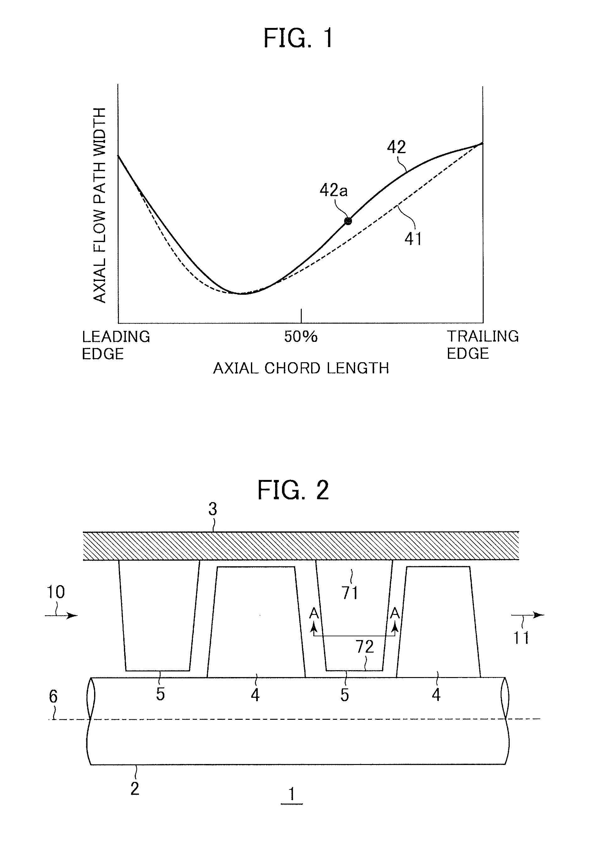
[0024]FIG. 2 is a partial transverse sectional view of a multistage axial compressor to which an airfoil of the present invention is applied.

[0025]An axial compressor 1 includes a rotating rotor 2 to which a plurality of rotor blades 4 are attached and a casing 3 to which a plurality of stator vanes 5 are attached. An annular flow path is defined by the rotor 2 and the casing 3. The rotor blades 4 and the stator vanes 5 are alternately arranged in an axial direction. A single row of the rotor blades 4 and a single row of the stator vanes 5 constitute a stage. The rotor 2 is driven by a drive source (not shown) such as a motor or a turbine installed to have the same axis of rotation 6. An inlet flow 10 passes through the rotor blades 4 and the stator vanes 5 while being reduced in speed, and becomes a high temperature and pressure outlet flow 11.

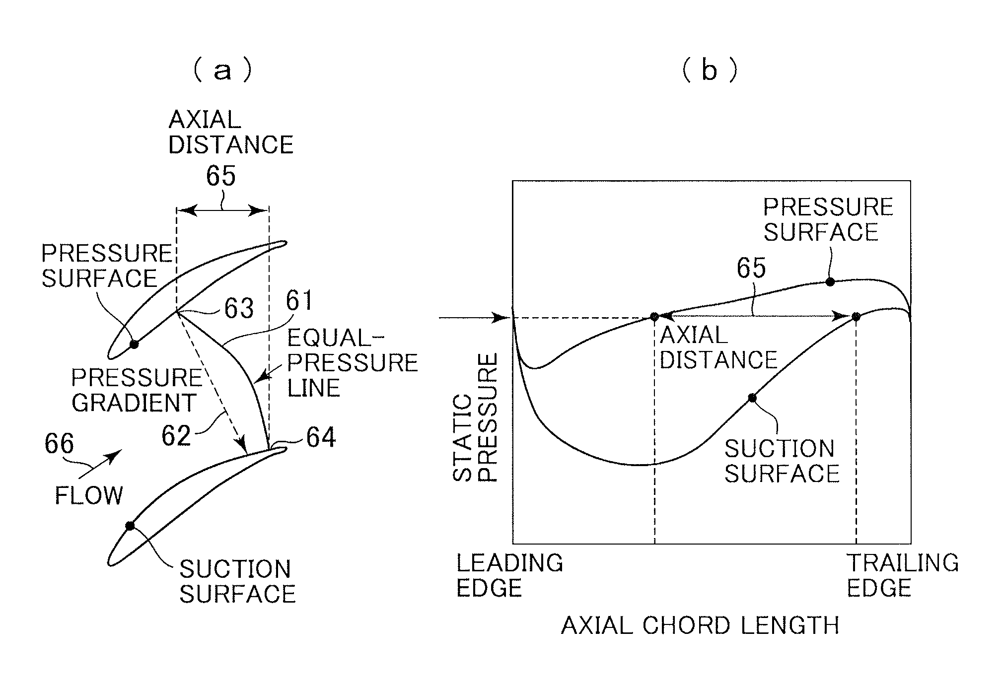
[0026]An axial compressor is one in which rotor blades apply kinetic energy to an inlet flow and stator vanes change the direction of the fl...


PUM

PropertyMeasurementUnit
pressureaaaaaaaaaa
widthaaaaaaaaaa
axial distanceaaaaaaaaaa

Abstract

An axial compressor includes a plurality of stator vanes attached to an inner surface of a casing defining an annular flow path and a plurality of rotor blades attached to a rotating rotor defining the annular flow path. A flow path is defined between a pressure surface of a stator vane and a suction surface of a stator vane, the vanes being circumferentially adjacent to each other, or between a pressure surface of a rotor blade and a suction surface of a rotor blade, the blades being circumferentially adjacent to each other. The flow path is formed so that a throat portion at which a flow path width is minimized is provided on the upstream side of 50% of an axial chord length.

Description

BACKGROUND OF THE INVENTION[0001]1. Field of the Invention[0002]The present invention relates generally to axial compressors for gas turbines and industrial applications, and in particular to an axial compressor having high-performance airfoils.[0003]2. Description of the Related Art[0004]NACA 65 series airfoils have heretofore been applied to subsonic airfoils located on the downstream side in an axial compressor. As described in “Aerodynamic Design of Axial-Flow Compressors”, National Aeronautics and Space Administration, 1965, (NACA, SP-36), the NACA 65 series airfoils are developed by an organized and comprehensive experimental research using a Wind Tunnel. In recent years, axial compressors have required higher loading combining a higher pressure ratio with cost reduction resulting from a reduction in the number of stages. A subsonic airfoil in the downstream stage of a high loaded compressor increases a secondary flow due to the growth of an endwall boundary layer. Therefore, ...

Claims


Application Information

Patent Timeline
Patent Type & Authority Patents(United States)
IPC IPC(8): F04D29/32F04D29/54
CPCF04D29/542F04D29/324F04D29/544Y10T29/49316F05B2240/123F05B2240/301
Inventor TAKAHASHI, YASUOMYOREN, CHIHIRO
Owner MITSUBISHI POWER LTD
Why Eureka
Try Eureka