Apparatus for improving refrigeration capacity

a technology of mechanical refrigeration and apparatus, applied in refrigeration machines, lighting and heating apparatus, refrigeration safety arrangements, etc., can solve the problems of flash gas damage to no hope of suppressing, and no hope of reducing the effect of flash gas on the liquid refrigerant pump

Active Publication Date: 2016-04-05
KOLARICH ROBERT
View PDF13 Cites 3 Cited by
  • Summary
  • Abstract
  • Description
  • Claims
  • Application Information

AI Technical Summary

Benefits of technology

[0015]An object of the present invention is to provide for a novel refrigeration system of the compression type, with improved efficiency.
[0016]A further object of the present invention is to provide for a novel refrigeration system in which the refrigeration capacity is maximized.
[0017]A still further object of the present invention is to economically suppress the formation of “flash gas” in refrigeration systems without impairing refrigeration capacity and efficiency.
[0020]A still further object of the present invention is to provide a system that is easily retrofitted to an operational refrigeration system.
[0021]A still further object of the present invention is to provide a system that will allow the original refrigeration system to operate properly whether the present invention is in operation or out of operation.
[0022]A still further object of the present invention is to put into one package a liquid refrigerant pumping system that proactively prevents pump cavitation.

Problems solved by technology

Additionally, the prior art identified the disastrous effect that flash gas has on the liquid refrigerant pump if it is allowed to enter the pump through the pump inlet.
Excess flash gas entering the liquid refrigerant pump will cause cavitation; since vaporous refrigerant cannot be returned to its liquid state by means of a liquid refrigerant pump, there will consequently be no hope of suppressing flash gas in the conduit leading to the refrigerant expansion device by means of said liquid refrigerant pump.
Additionally, cavitation causes pump damage.
Past attempts to implement the prior art have not always supplied the liquid refrigerant pump with its required NPSH.
Space constraints often do not permit a vertical column of vapor free liquid refrigerant that is high enough above the center line of the liquid refrigerant pump inlet to insure that the required NPSH is available to the liquid refrigerant pump.

Method used


Image

  • Apparatus for improving refrigeration capacity
  • Apparatus for improving refrigeration capacity
  • Apparatus for improving refrigeration capacity

Examples


Embodiment Construction

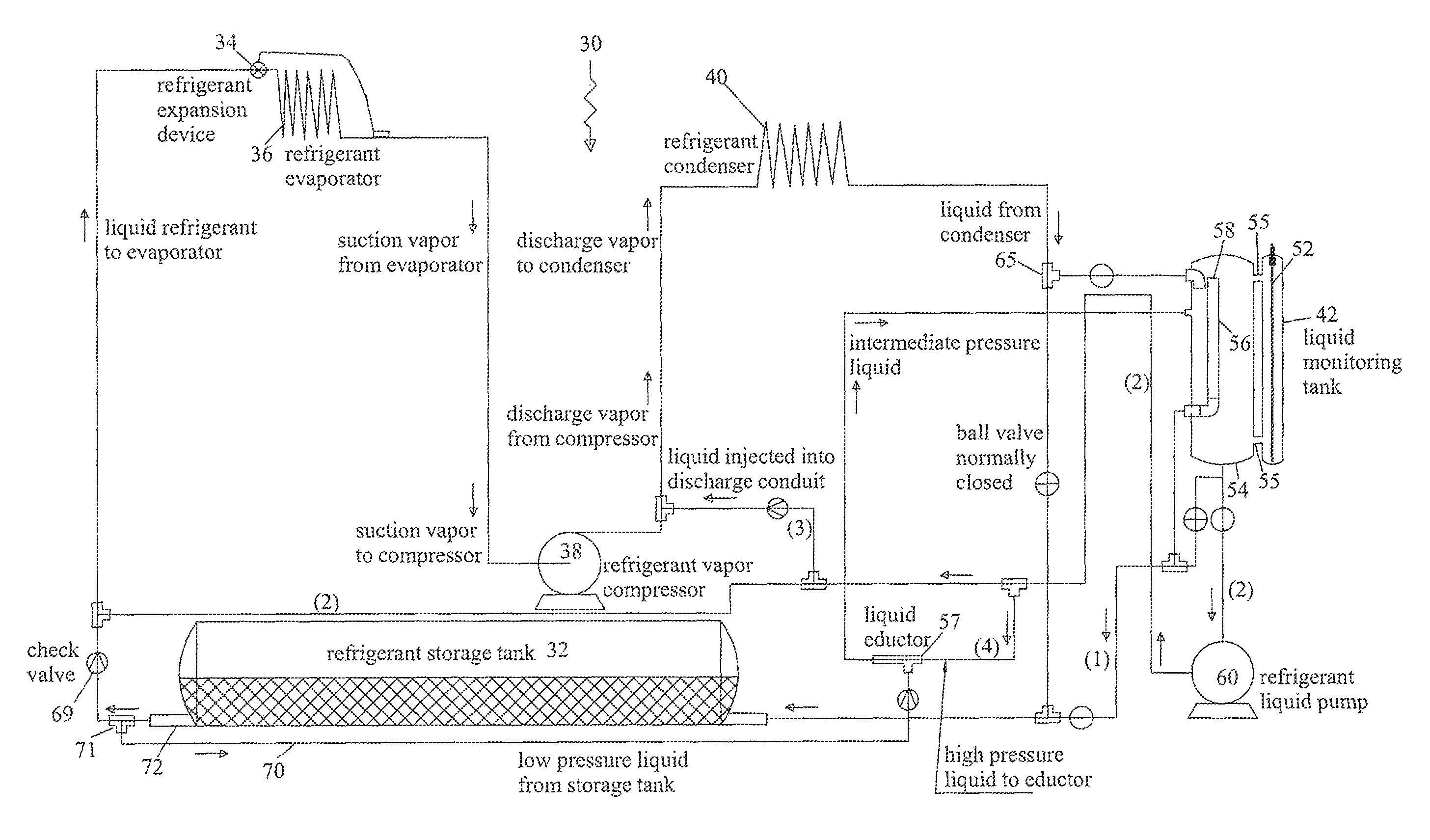
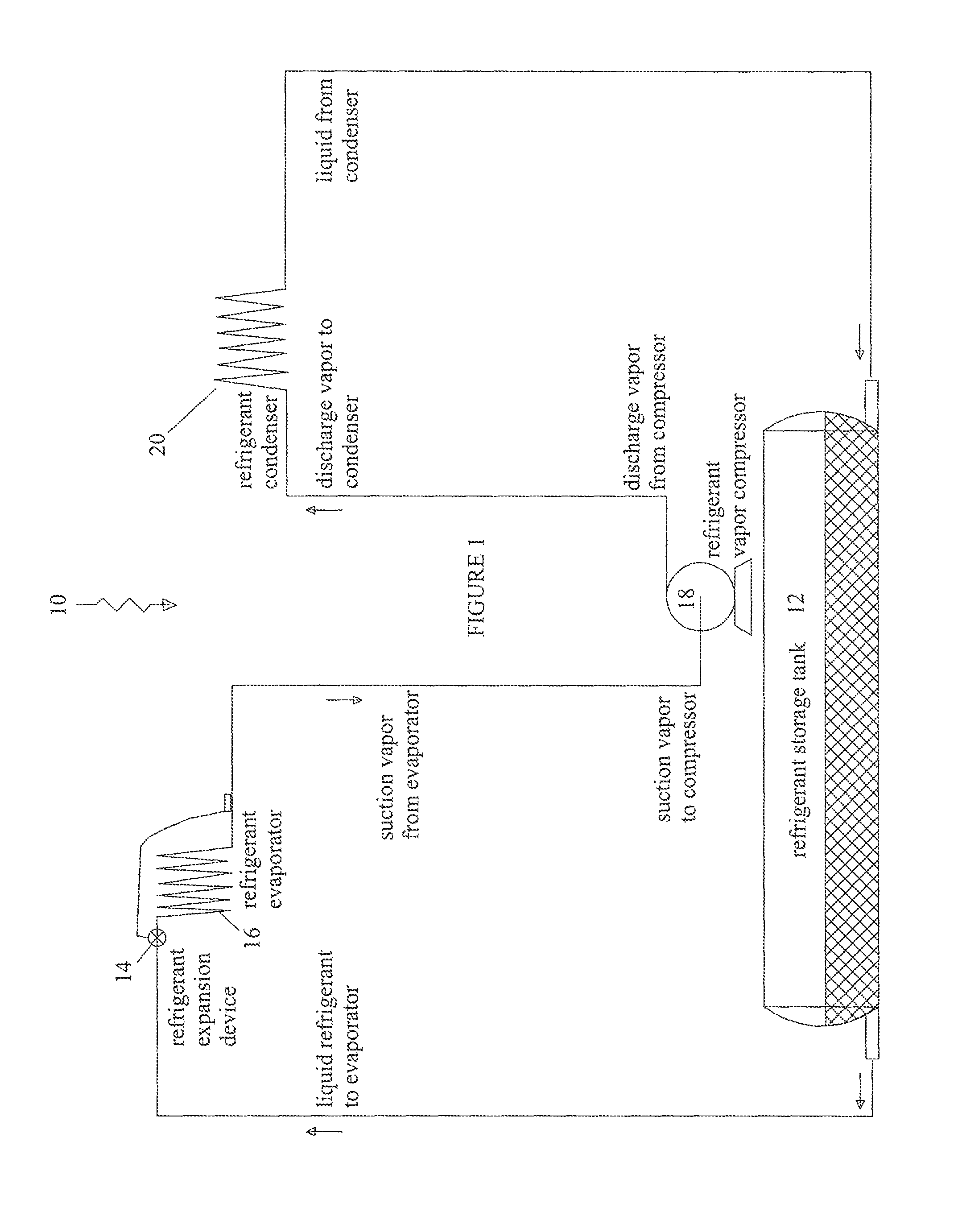
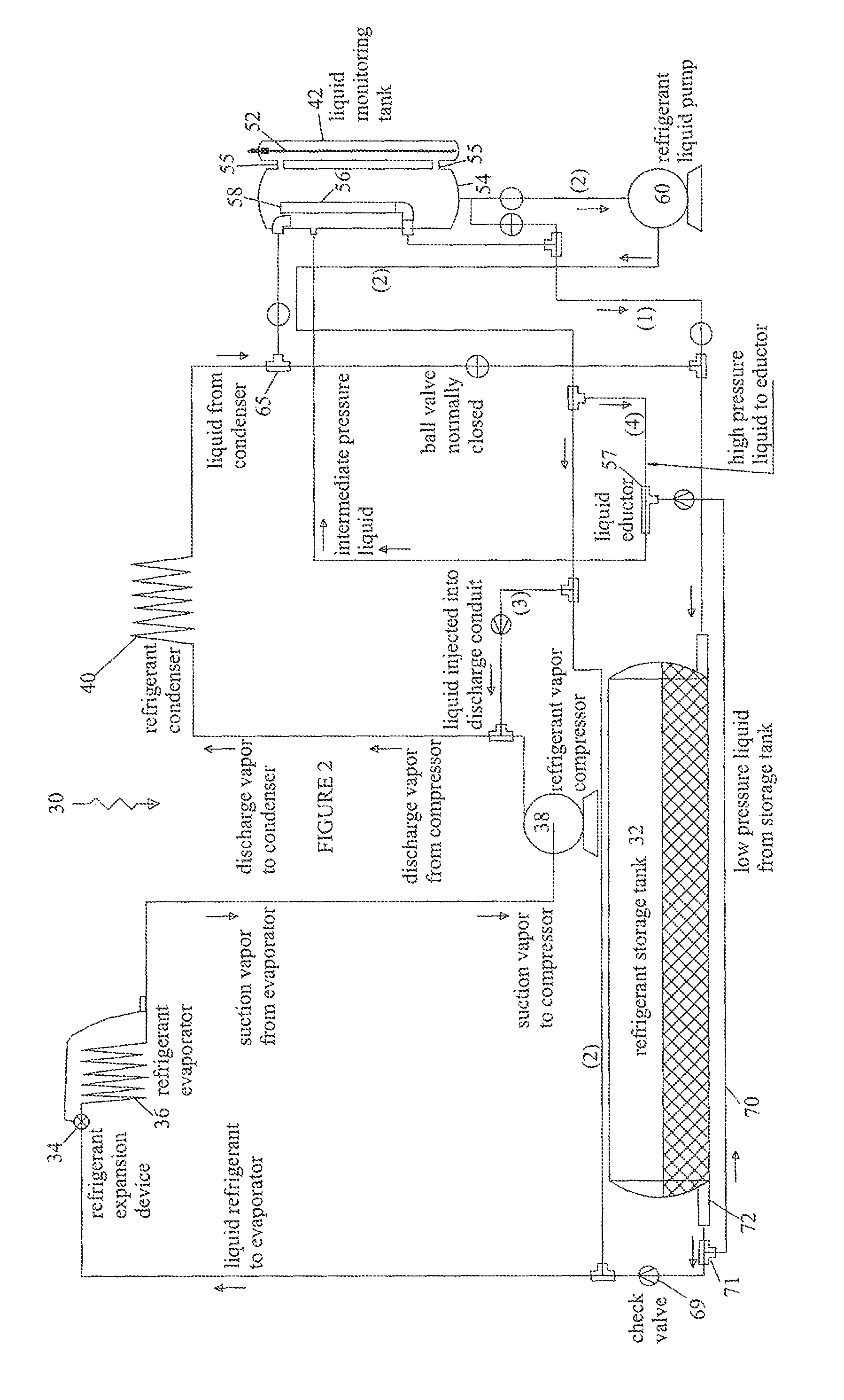
[0029]FIG. 1 is a schematic illustration of a typical refrigeration system 10 of the prior art. It consists of several main constituents. Initially there is a refrigerant storage tank 12 in which the flowing liquid refrigerant is temporarily stored. There is a refrigerant expansion device 14 which converts the liquid refrigerant to vapor in the refrigerant evaporator 16. The refrigerant vapor is then directed by means of a refrigerant vapor compressor 18 to a refrigerant condenser 20 where the vapor is then converted from vapor to liquid and returned to the refrigerant storage tank. In this system of the prior art, discharge vapor and liquid pressures and temperatures must be maintained at minimum levels that are high enough to provide the refrigerant system's expansion devices with liquid refrigerant at pressures and temperatures that will provide the required amount of heat removal. Unless proper pressure and temperature ranges are maintained, “flash gas” will develop in the liqui...


PUM

PropertyMeasurementUnit
pressureaaaaaaaaaa
heightaaaaaaaaaa
areasaaaaaaaaaa

Abstract

A refrigeration, air conditioning or other cooling system is disclosed. The refrigeration system includes a refrigerant storage tank fluidly connected to a refrigerant expansion device which is fluidly connected to a refrigerant evaporator for absorbing ambient heat, a refrigerant vapor compressor fluidly connected to the refrigerant evaporator and a refrigerant condenser fluidly connected to the refrigerant compressor and the refrigerant storage tank. A liquid refrigerant pump and eductor are included in the system along with a refrigerant receiving tank and associated controls that maintain the appropriate Net Positive Suction Head at the inlet to the pump along with proper flow and pressure control in the system.

Description

PRIORITY CLAIM[0001]Applicant claims the benefit of provisional application 61 / 742,558, filed Aug. 14, 2012. The disclosure set forth in said provisional application is incorporated herein by reference.BACKGROUND OF THE INVENTION[0002]1. Field of the Invention[0003]This invention generally relates to the modification of mechanical refrigeration or air conditioning systems to include a complete, integrated liquid refrigerant pumping system. Applicant's system also proactively protects the refrigerant pump from damage related to cavitation and the loss of lubrication as result of vaporous refrigerant entering the pump, by consistently supplying the pump with liquid refrigerant above its NPSH requirement. Applicant's system also contains itself within a greatly reduced footprint allowing the system to be installed or retrofitted in spatially limited areas.[0004]2. Description of the Prior Art[0005]In the operation of commercial freezers, refrigerators, air conditioners, and other compr...

Claims


Application Information

Patent Timeline
Patent Type & Authority Patents(United States)
IPC IPC(8): F25B49/02B23P15/26
CPCB23P15/26F25B49/02Y10T29/49352F25B41/00F25B45/00F25B49/005F25B2341/0012F25B2400/16F25B2700/04
Inventor KOLARICH, ROBERT
Owner KOLARICH ROBERT
Why Eureka
Try Eureka