Blank chamber and housing

a technology of a gun chamber and a housing, which is applied in the field of components of a firearmlike device, can solve the problems of the structure and regulations of non-guns that are subject to the penalties, regulations, and regulations of live ammunition shooting firearms

Active Publication Date: 2016-04-05
HISCOCK JASON P
View PDF22 Cites 2 Cited by
  • Summary
  • Abstract
  • Description
  • Claims
  • Application Information

AI Technical Summary

Benefits of technology

[0025]A blank handling device is provided for receiving and firing a blank cartridge for use in a non-gun. The handling device includes a housing having a blank receiving chamber sized and configured for holding the blank during firing. The blank receiving chamber includes a first axis and a first diameter. A gas discharging passageway capable of being coupled to a barrel of a non-gun, is provided that has a second axis and a second diameter. A gas flow passageway is fluidly coupled to and extends between the blank receiving chamber and the gas flow passageway for conducting gasses discharged by the firing of the blank cartridge between the blank receiving chamber and the gas discharging passageway. The gas flow passageway has a third axis and a third diameter. The third diameter is less than the first diameter for preventing the passage through the gas flow passageway of a projectile discharged in the blank receiving chamber.

Problems solved by technology

The ability of such a non-gun's components to be tampered with and converted into a gun that is capable of firing ammunition is a quality that will often cause a particular non-gun to lose its designation as a non-gun, and that may cause the non-gun to be subjected to the penalties, structures and regulations attendant to live ammunition shooting firearms.

Method used


Image

  • Blank chamber and housing
  • Blank chamber and housing
  • Blank chamber and housing

Examples


Embodiment Construction

[0058]Before delving into a description of the present invention, it is useful to review the various components of a typical firearm, to help provide context to the description of the present invention.

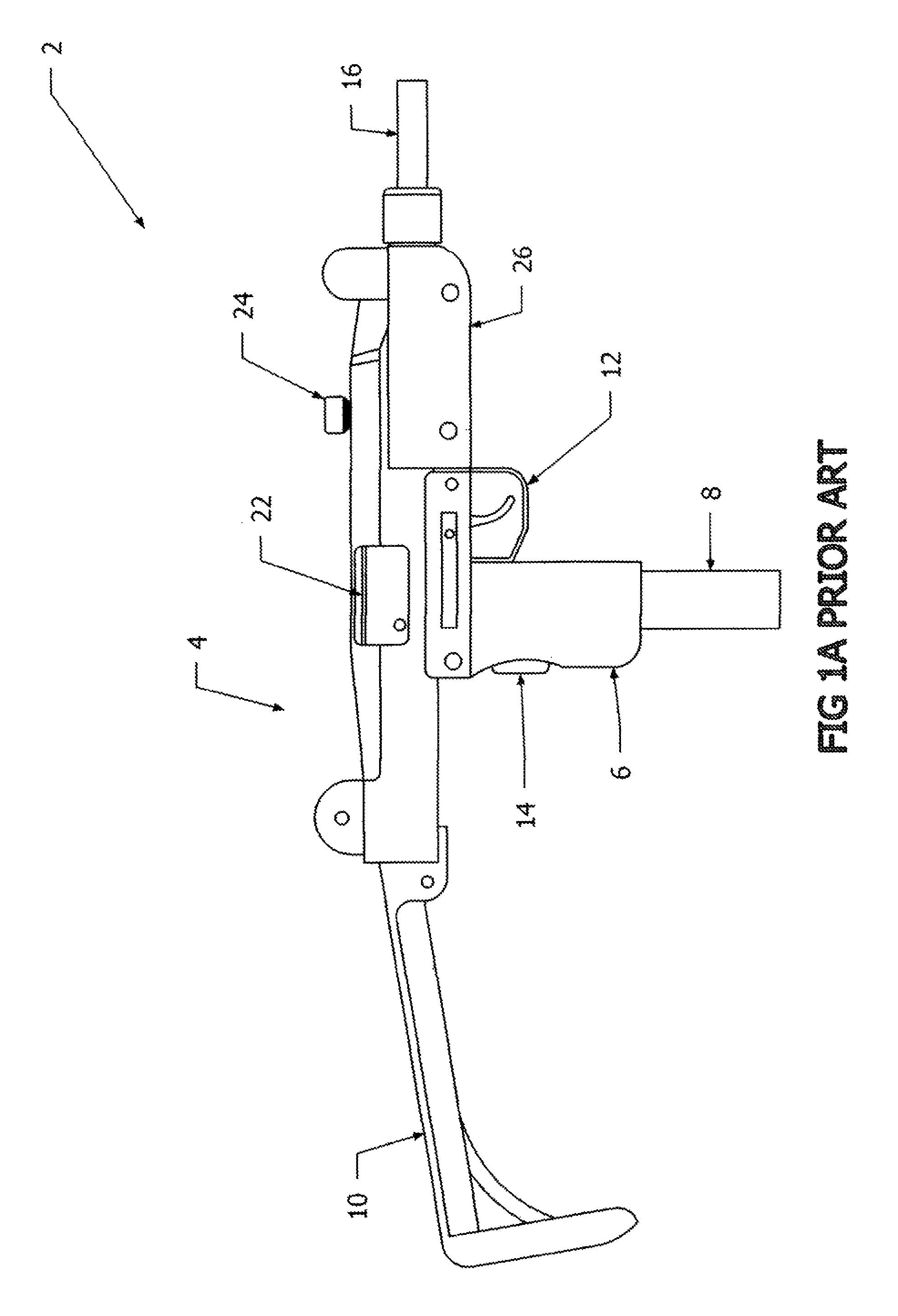
[0059]In FIG. 1A, a schematic drawing of a prior art weapon is shown. In particular, the weapon shown in FIG. 1A is an Uzi submachine gun that is the subject of U.S. Pat. No. 4,335,643, that issued on 22 Jun. 1982. The description of the machine gun and the manner in which it operates is incorporated herein by reference.

[0060]The machine gun 2 shown in FIG. 1A includes an elongated receiver 4, that generally contains the various springs, bolts, slides, etc., that handle the passage of a cartridge and passage from a magazine, to the receiver and then upon ejection from the gun. Although the weapon 2 shown in FIG. 1A is a “gun” capable of firing projectiles, it will be appreciated that the feature described in connection with the Uzi submachine gun 2 of FIG. 1A could be common with a bl...


PUM


Abstract

A blank handling device is provided for receiving and firing a blank cartridge for use in a non-gun. The handling device includes a housing having a blank receiving chamber sized and configured for holding the blank during firing. The blank receiving chamber includes a first axis and a first diameter. A gas discharging passageway capable of being coupled to a barrel of a non-gun, is provided that has a second axis and a second diameter. A gas flow passageway is fluidly coupled to and extends between the blank receiving chamber and the gas flow passageway for conducting gasses discharged by the firing of the blank cartridge between the blank receiving chamber and the gas discharging passageway. The gas flow passageway has a third axis and a third diameter. The third diameter is less than the first diameter for preventing the passage through the gas flow passageway of a projectile discharged in the blank receiving chamber.

Description

PRIORITY STATEMENT[0001]The present invention claims benefit of priority to U.S. Provisional Patent Application No. 61 / 859,831 that was filed on 30 Jul. 2013 and which is fully incorporated herein by reference.I. TECHNICAL FIELD OF THE INVENTION[0002]The present invention relates to firearm-like devices, and more particularly, to a component of a firearm-like device that is designed for firing non-projectile containing blanks, and that is generally incapable of firing projectile containing live ammunition.II. BACKGROUND OF THE INVENTION[0003]For the purposes of definition, it is important first to distinguish “guns” and “non-guns”. As used in this application, the term “gun” or “firearm” will normally be associated with a device that is capable of firing live ammunition, that results in a projectile being projected out of the barrel of the device. The term “non-gun” or “replica” will be used in this application to denote a device that, although having an appearance of a gun, is not ...

Claims


Application Information

Patent Timeline
Patent Type & Authority Patents(United States)
IPC IPC(8): F41A33/00F41A21/26F41A21/12F41A33/04
CPCF41A21/12F41A21/26F41A33/04
Inventor HISCOCK, JASON P.
Owner HISCOCK JASON P
Why Eureka
Try Eureka