System and method for identifying and locating instances of a shape under large variations in linear degrees of freedom and/or stroke widths

Active Publication Date: 2016-04-05
COGNEX CORP
View PDF20 Cites 3 Cited by
  • Summary
  • Abstract
  • Description
  • Claims
  • Application Information

AI Technical Summary

Benefits of technology

[0010]The procedures may also be utilized during run time to identify fiducials that are known

Problems solved by technology

Where sufficiently serious defects are noted, a part of a surface is marked as unacceptable/defective.
This may substantially increase the time required to train a machine vision sy

Method used


Image

  • System and method for identifying and locating instances of a shape under large variations in linear degrees of freedom and/or stroke widths
  • System and method for identifying and locating instances of a shape under large variations in linear degrees of freedom and/or stroke widths
  • System and method for identifying and locating instances of a shape under large variations in linear degrees of freedom and/or stroke widths

Examples


Embodiment Construction

A. Machine Vision System

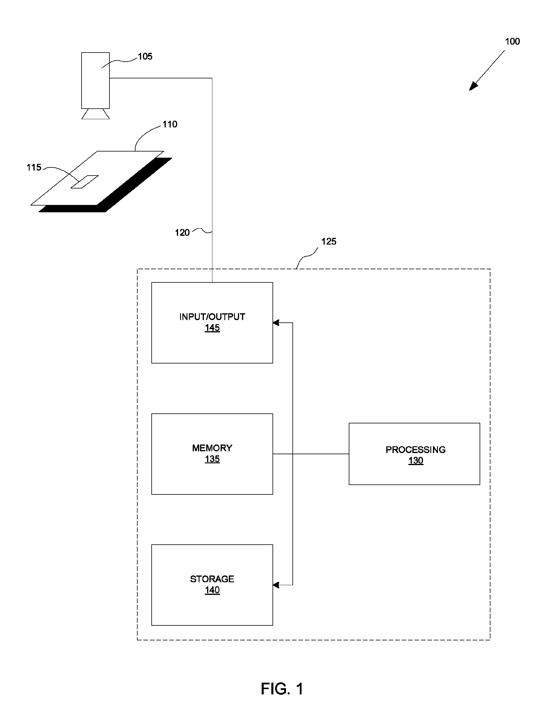
[0022]FIG. 1 is a schematic block diagram of a machine vision system 100 that may be utilized to practice the principles of the present invention in accordance with an illustrative embodiment of the present invention. The machine vision system 100 includes a capturing device 105 that generates an image of an object 110 having one or more features 115. The capturing device 105 may comprise a conventional video camera or scanner. Such a video camera may be a charge coupled device (CCD) or other system for obtaining appropriate image information. Image data (or pixels) generated by the capturing device 105 represents an image intensity, for example, color or brightness of each point in the scene within the resolution of the capturing device 105. The capturing device 105 transmits a digital image data via a communications path 120 to an image analysis system 125. The image analysis system 125 may comprise a conventional digital data processor, such as the vision ...


PUM


Abstract

A system and method for identifying and locating instances of a shape under large variations in linear degrees of freedom is provided. The invention extracts boundary segments from an image and generates potential match candidates for boundary models based on the extracted boundary segments. The invention also extracts skeletal segments from the obtained image. Potential match candidates are then generated for skeletal models based on the extracted skeletal segments. Once the match candidates for the boundary models and skeletal models have been generated, the present invention then corresponds the various boundary segments and outputs a best correspondence. The output from the present invention may be utilized by a user to signify acceptance of the various correspondences located by the present invention. These correspondences may then be utilized to train a machine vision system.

Description

BACKGROUND OF THE INVENTION[0001]1. Field of the Invention[0002]The present invention relates to machine vision systems and, more specifically, to identifying and locating instances of a shape under large variations in linear degrees of freedom and / or stroke widths in machine vision systems.[0003]2. Background Information[0004]The use of advanced machine vision systems and their underlying software is increasingly employed in a variety of manufacturing and quality control processes. Machine vision enables quicker, more accurate and repeatable results to be obtained in the production of both mass-produced and custom products. Basic machine vision systems include one or more cameras (typically having solid-state charge couple device (CCD) imaging elements) directed at an area of interest, frame grabber / image processing elements that capture and transmit CCD images, a computer and display for running the machine vision software application and manipulating the captured images, and appr...

Claims


Application Information

Patent Timeline
IPC IPC(8): G06K9/46G06T7/00G06V10/34G06V10/44G06V10/772
CPCG06K9/4604G06T7/0042G06T2207/20081G06T2207/30164G06T7/73G06V10/34G06V10/752G06V10/44G06V2201/06G06V10/772G06F18/28
Inventor BOGAN, NATHANIEL ROCKWOODMOTOYAMA, TOSHIMITSU
Owner COGNEX CORP
Why Eureka
Try Eureka