Supply voltage drift insensitive digitally controlled oscillator and phase locked loop circuit

a digital control and oscillator technology, applied in the field of oscillators, can solve the problems of affecting the operation of the device, the oscillator oscillator oscillator oscillator oscillator oscillator oscillator oscillator oscillator oscillator oscillator oscillator oscillator oscillator oscillator oscillator oscillator oscillator oscillator oscillator oscillator oscillator oscillator oscillator oscillator oscillator oscill

Active Publication Date: 2016-04-05
MEDIATEK INC
View PDF23 Cites 5 Cited by
  • Summary
  • Abstract
  • Description
  • Claims
  • Application Information

AI Technical Summary

Benefits of technology

[0006]Digitally controlled oscillators and phase locked loop circuits are provided. An exemplary embodiment of a digitally controlled oscillator comprises a ring oscillator and a first supplementary circuit. The ring oscillator is coupled to a supply voltage and generates a signal oscillated at an oscillating frequency. The oscillating frequency is controlled by a digital code and further varies with a supply voltage drift in a first direction. The first supplementary circuit is coupled to the ring oscillator and facilitates the oscillating frequency to vary with the supply voltage drift in a second direction reverse to the first direction.
[0007]An exemplary embodiment of a phase locked loop circuit comprises a phase frequency detector, a digital loop filter, a digitally controlled oscillator and a divider. The phase frequency detector detects a phase difference between a feedback signal and a reference signal, and generates a phase error signal in response to the detected phase difference. The digital loop filter outputs a digital code based on the phase error signal. The digitally controlled oscillator is coupled to a supply voltage, receives the digital code and generates a signal oscillated at an oscillating frequency in response to the digital code. The divider receives the signal generated by the digitally controlled oscillator to generate the feedback signal. The digitally controlled oscillator comprises a ring oscillator and a first supplementary circuit coupled to the ring oscillator for facilitating the oscillating frequency to decrease as the supply voltage increases.

Problems solved by technology

However, the oscillation frequency of an oscillator is generally unstable.
In particular, the oscillation frequency varies with ambient temperature and supply-voltage drift, which affects the operation of the device.

Method used


Image

  • Supply voltage drift insensitive digitally controlled oscillator and phase locked loop circuit
  • Supply voltage drift insensitive digitally controlled oscillator and phase locked loop circuit
  • Supply voltage drift insensitive digitally controlled oscillator and phase locked loop circuit

Examples


Embodiment Construction

[0020]The following description is of the best-contemplated mode of carrying out the invention. This description is made for the purpose of illustrating the general principles of the invention and should not be taken in a limiting sense. The scope of the invention is best determined by reference to the appended claims.

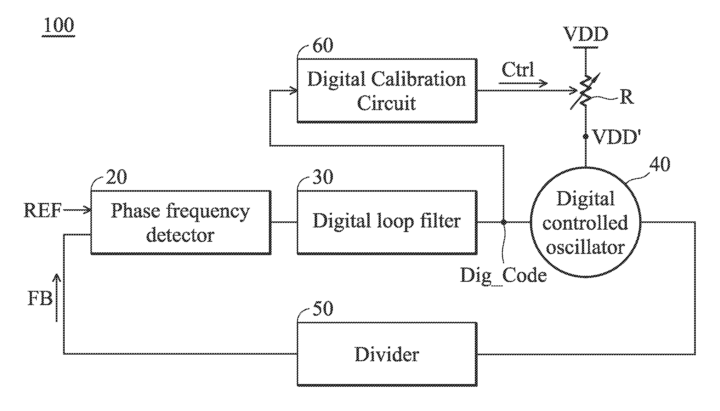
[0021]FIG. 1 shows a block diagram of a phase locked loop circuit according to an embodiment of the invention. According to an embodiment of the invention, the phase locked loop circuit 100 may be an all digital phase locked loop. The phase locked loop circuit 100 may basically comprise a phase frequency detector 20, a digital loop filter 30, a digitally controlled oscillator 40 and a divider 50. The phase frequency detector 20 detects a phase difference between a feedback signal FB and a reference signal REF, and generates a phase error signal in response to the detected phase difference. The digital loop filter 30 outputs a digital code Dig_Code based on the phase er...


PUM


Abstract

A digitally controlled oscillator includes a ring oscillator and a first supplementary circuit. The ring oscillator is coupled to a supply voltage and generates a signal oscillated at an oscillating frequency. The oscillating frequency is controlled by a digital code and further varies with a supply voltage drift in a first direction. The first supplementary circuit is coupled to the ring oscillator and facilitates the oscillating frequency to vary with the supply voltage drift in a second direction reverse to the first direction.

Description

BACKGROUND OF THE INVENTION[0001]1. Field of the Invention[0002]The invention relates to an oscillator, and more particularly, to an oscillator that is stable and insensitive to supply-voltage drift.[0003]2. Description of the Related Art[0004]An oscillator is used in electronic circuits to generate precise clock signals. However, the oscillation frequency of an oscillator is generally unstable. In particular, the oscillation frequency varies with ambient temperature and supply-voltage drift, which affects the operation of the device.[0005]Thus, it is desirable to design a novel oscillator that is stable and insensitive to supply-voltage drift.BRIEF SUMMARY OF THE INVENTION[0006]Digitally controlled oscillators and phase locked loop circuits are provided. An exemplary embodiment of a digitally controlled oscillator comprises a ring oscillator and a first supplementary circuit. The ring oscillator is coupled to a supply voltage and generates a signal oscillated at an oscillating freq...

Claims


Application Information

Patent Timeline
Patent Type & Authority Patents(United States)
IPC IPC(8): H03K3/03H03L1/00H03L7/099H03L7/14
CPCH03L1/00H03L7/0995H03K3/0315H03L7/14H03L2207/06H03L2207/08
Inventor HUANG, YI-CHIEHWANG, PING-YING
Owner MEDIATEK INC
Why Eureka
Try Eureka