One-star system for feeding and discharging containers for processing machines

a technology of feeding and discharging containers and processing machines, applied in applications, liquid handling, other domestic articles, etc., can solve the problems of large design complexity of mounting and driving the rotors, large blind angle, and large space occupation, and achieve the effect of increasing processing tim

Inactive Publication Date: 2016-04-26
KRONES AG
View PDF80 Cites 2 Cited by
  • Summary
  • Abstract
  • Description
  • Claims
  • Application Information

AI Technical Summary

Benefits of technology

[0006]Given the problems discussed in prior art, it is one aspect of the present disclosure to increase the processing time at the smallest possible diameter of the processing wheel and also to provide a robust option for processing containers.
[0034]The stretching rod, typically being used for stretching the preforms fed and previously thermally conditioned, can also serve to entrain the containers with the motions of the stretching rod. This creates an additional advantage in that the stretching rod is anyway typically intended to perform relatively large motions in terms of stretching so that the motion of the containers affixed to the stretching rod requires virtually no additional distances of the stretching rod. This in turn means, in particular with respect to vertical / axial motions, that the stretching rod in connection with pressure variations can advantageous move the containers. In general, but also in particular for this, the motions of the blowing nozzle and those of the stretching rod can be coupled to each other. In particular, the drive for the stretching rod is then used for the motion of the container.
[0035]In addition, the processing element of the processing station in the processing device as described above can comprise a clamping device for gripping the containers. At the blowing nozzle or at the stretching rod as described above, an additional clamping element or gripper element can therefore be attached at the lower end to create an additional clamping effect.

Problems solved by technology

In such devices, however, the feeding and discharge wheels / stars require a relatively large amount of space.
Furthermore, the design complexity for mounting and driving the rotors is significant.
In addition, the problem occurs that the feed location and the removal location are stretched relatively far apart, so that a relatively large blind angle is created due to the use of the two wheels.
However, such a solution is usually very expensive.

Method used


Image

  • One-star system for feeding and discharging containers for processing machines
  • One-star system for feeding and discharging containers for processing machines
  • One-star system for feeding and discharging containers for processing machines

Examples


Embodiment Construction

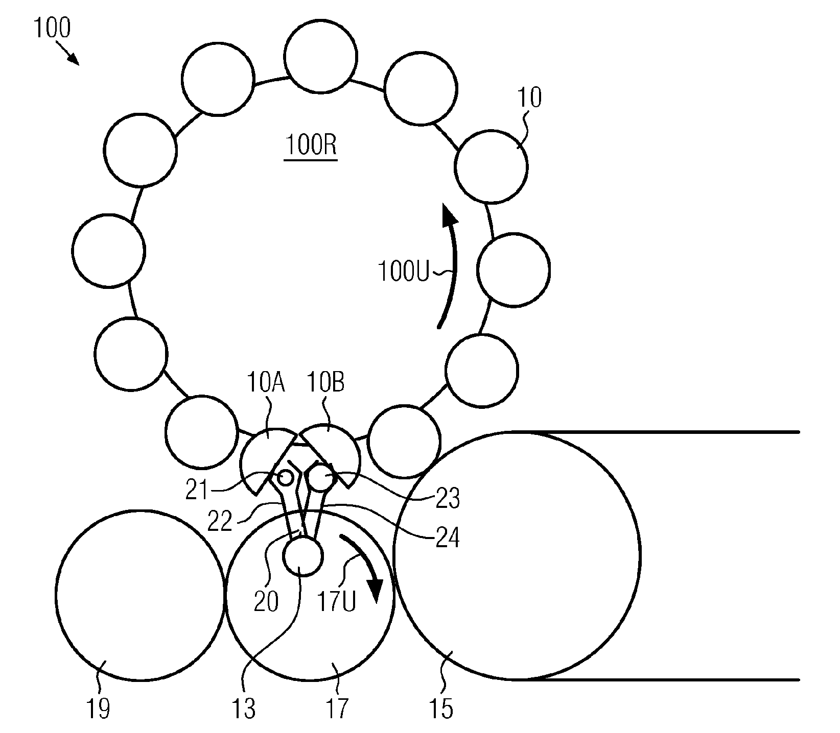
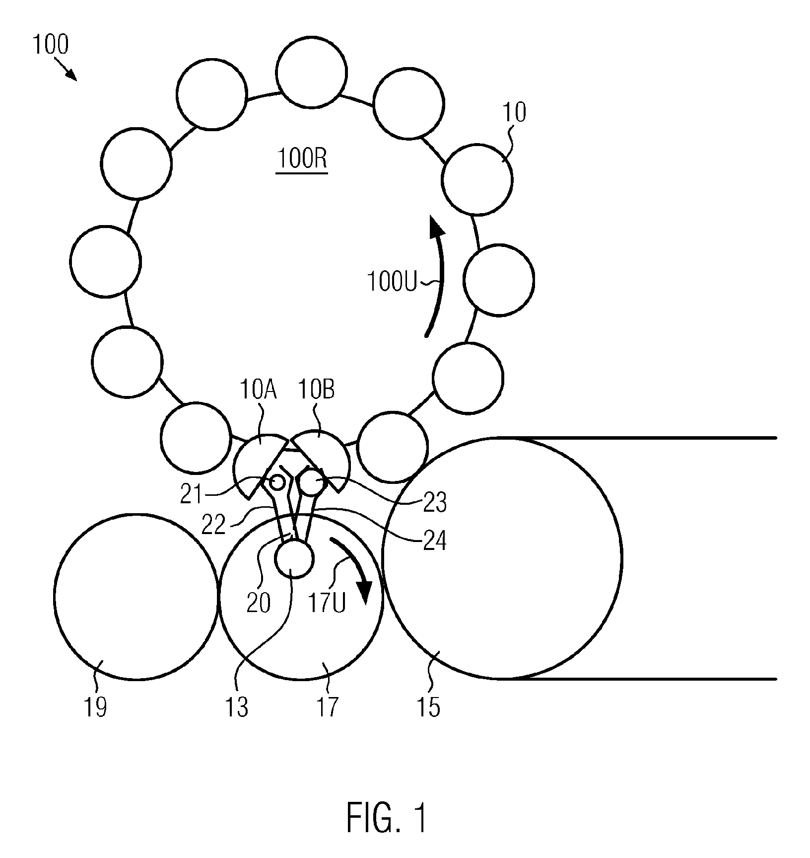
[0087]FIG. 1 shows an embodiment of a processing device 100 according to the disclosure being designed as a rotary blow-molding machine with a blowing wheel. The processing device 100, drawn purely by way of example, in FIG. 1 bears twelve processing stations 10 that are in the following FIGS. 3B-4A described in more detail. By way of example, a direction of rotation of the processing device 100 with a processing wheel 100R is indicated by arrow 100U. By way of example, one of the processing stations 10 is shown in the unfolded state. In this, containers are fed to or respectively removed from the processing station 10, in particular their halves 10A and 10B, by only one feed and removal star 17, in short referred to as a star. The direction of rotation of the feed and removal star 17 is indicated by arrow 17U. Furthermore, FIG. 1 shows a pre-processing element 15, for example a furnace, for thermal conditioning of containers to be processed before they are taken to a processing sta...


PUM

PropertyMeasurementUnit
angleaaaaaaaaaa
angleaaaaaaaaaa
angleaaaaaaaaaa

Abstract

The invention relates to a processing machine having a processing wheel, which is in particular continuously driven, comprising at least one processing station for processing containers; comprising only one star for feeding and removing containers into and out of the processing device, which has at least two gripper elements for feeding containers to be processed to the processing station and for removing the processed containers from the processing station; wherein the processing station has a processing position within the processing station; characterized in that the processing station has at least one processing element processing a container, which is designed so that it can move the fed containers to be processed and / or the processed containers to be removed at least partially out of the processing position and / or into the processing position, in particular in a vertical or horizontal manner.

Description

CROSS-REFERENCE TO RELATED APPLICATION[0001]The present application is the United States national phase of International Patent Application No. PCT / EP2012 / 059109, filed May 16, 2012, which application claims priority of German Application No. 10 2011 079 078.0, filed Jul. 13, 2011. The priority application is incorporated herein by reference in its entirety.FIELD OF THE DISCLOSURE[0002]The disclosure relates to a processing device having a processing wheel such as for processing containers and receptacles.BACKGROUND[0003]Prior art discusses various devices for processing containers / receptacles. A typical example for this is blow-molding containers. In this, a preform, following thermal treatment / preconditioning, is transferred into a blow mold in a blow-molding station, and is there molded to a container by the application of a blowing pressure. A plurality of wheel-like, star-like carrier wheels is typically used as subcarriers. The feed wheels deliver the thermally preconditioned ...

Claims


Application Information

Patent Timeline
Patent Type & Authority Patents(United States)
IPC IPC(8): B29D22/00B67C7/00B67C3/22B65C9/00B29C49/42B65G47/86B29C35/08B29C49/58B29C49/12B29C49/06B29C49/36
CPCB29D22/003B29C49/421B29C49/4205B29C49/4289B65C9/00B67C3/22B67C7/004B29C49/06B29C49/12B29C49/36B29C49/4236B29C49/58B29C2035/0822B29C2035/0855B29C2049/4294B65G47/847Y02P70/271Y02P70/10B29C49/42069B29C49/42063B29C49/42095B29C49/42362B29C49/42855B29C2949/0715B29C49/6464B29C49/6466B29C49/6465B29C49/681B29C2049/7831B29C2049/7832
Inventor WINZINGER, FRANK
Owner KRONES AG
Why Eureka
Try Eureka