Fuel system diagnostics

a fuel system and diagnostic technology, applied in the field of fuel system diagnostics, can solve the problems of reducing fuel economy, consuming vehicle power, and allowing fuel vapor to escape into the atmosphere, so as to improve leak detection accuracy, reduce component cost, and increase the life of the electrically driven vacuum pump.

Active Publication Date: 2016-04-26
FORD GLOBAL TECH LLC
View PDF11 Cites 2 Cited by
  • Summary
  • Abstract
  • Description
  • Claims
  • Application Information

AI Technical Summary

Benefits of technology

[0004]However, the inventors herein have identified potential issues with such an approach. As one example, to perform the leak detection routine, the vacuum pump has to be operated, consuming vehicle power and reducing fuel economy. As another example, some leaks may be masked in the presence of negative pressure. If the leak goes undetected, exhaust emissions may be degraded.
[0007]In this way, vacuum pump operation can be synergistically coupled to a positive pressure fuel system leak test. By allowing positive pressure from the vacuum pump to be used for a fuel system leak test while a vacuum pump is already operating to provide vacuum to a vacuum-operated actuator, the electrically driven vacuum pump may be operated less frequently. By reducing the frequency of pump operation, an operational lifespan of the electrically driven vacuum pump may be increased. In addition, since fuel vapor does not pass through the pump, issues related to material incompatibility may not arise. By using the vacuum pump to also perform a negative pressure leak test, leaks masked by a positive pressure leak test may be identified during the negative pressure leak test, and vice versa, improving leak detection accuracy. By using the same pump for each of a positive pressure and negative pressure leak test, as well as for vacuum generation for other engine actuators, component reduction benefits are achieved.

Problems solved by technology

However, leaks in the emissions control system can inadvertently allow fuel vapors to escape to the atmosphere.
However, the inventors herein have identified potential issues with such an approach.
As one example, to perform the leak detection routine, the vacuum pump has to be operated, consuming vehicle power and reducing fuel economy.
If the leak goes undetected, exhaust emissions may be degraded.
In addition, since fuel vapor does not pass through the pump, issues related to material incompatibility may not arise.

Method used


Image

  • Fuel system diagnostics
  • Fuel system diagnostics
  • Fuel system diagnostics

Examples


Embodiment Construction

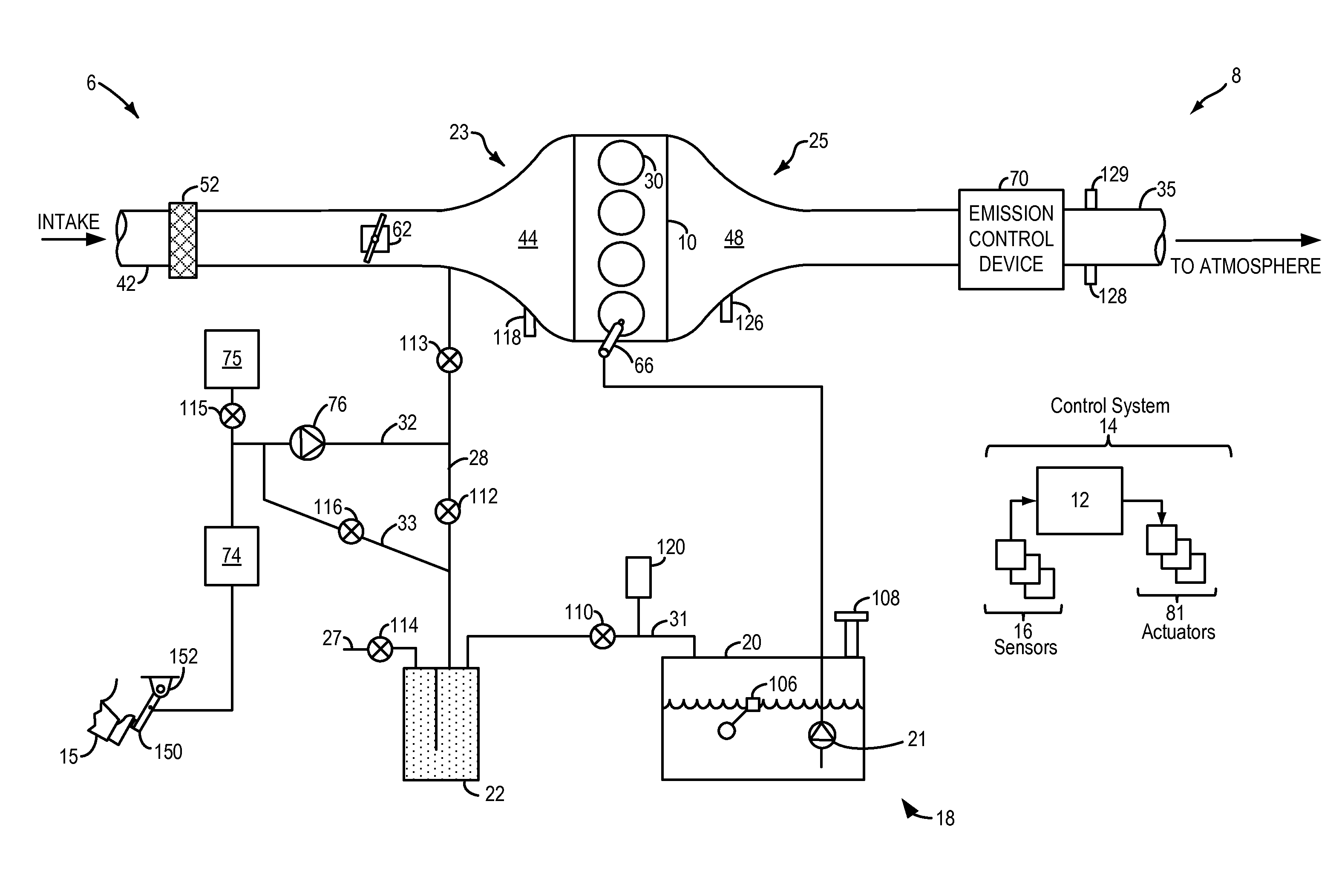
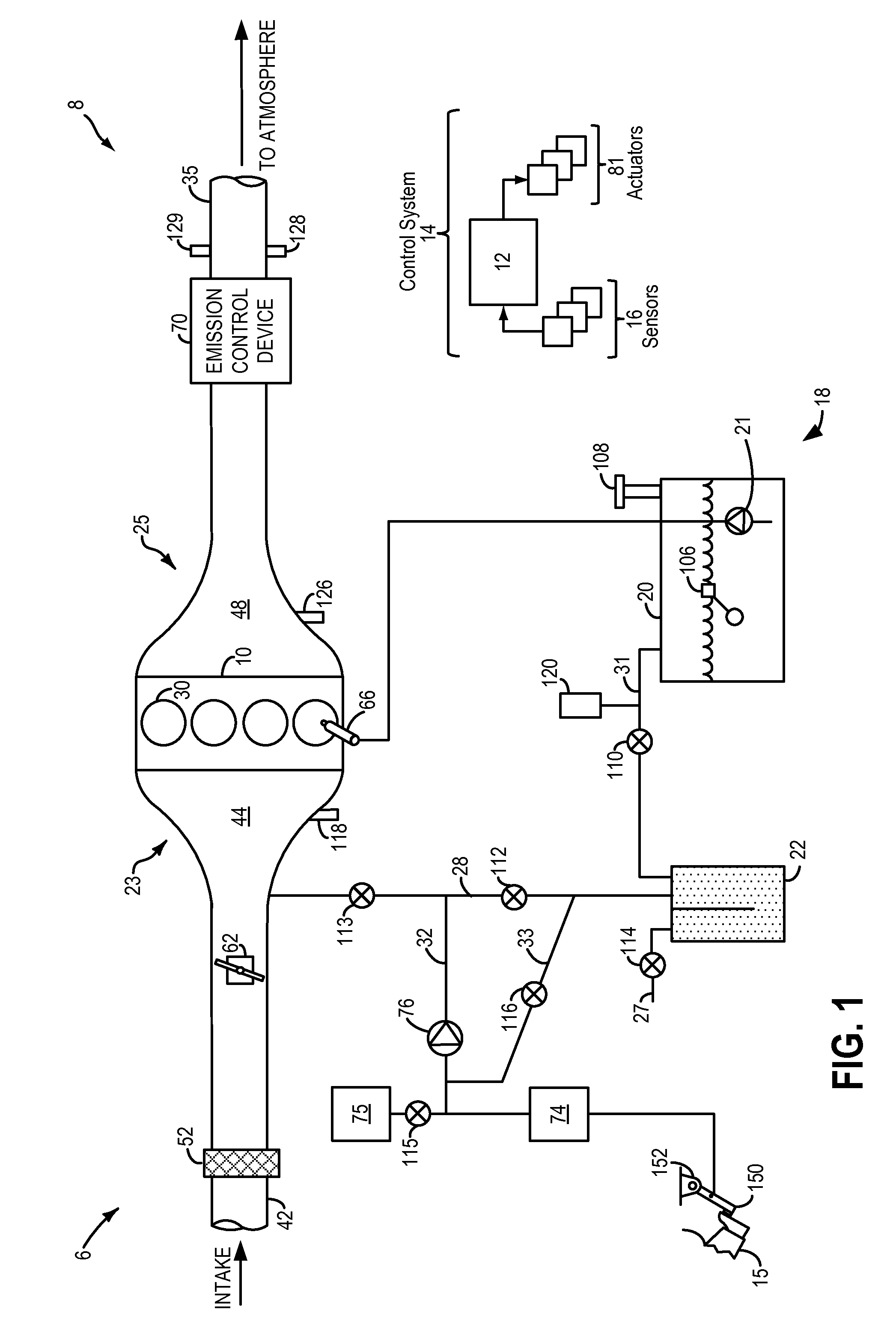
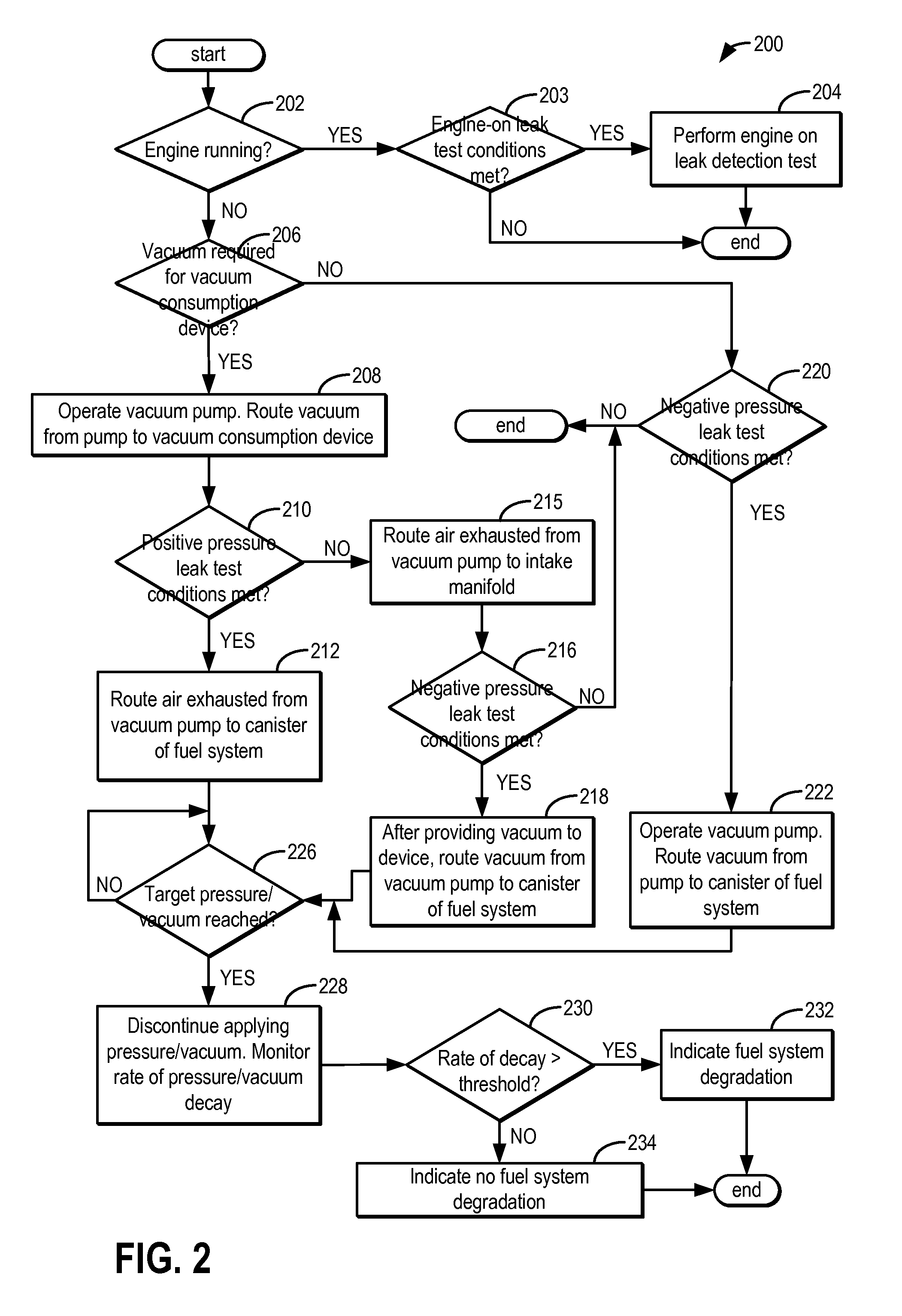
[0013]Methods and systems are provided for identifying leaks in a fuel system coupled to an engine, such as the fuel system of FIG. 1. A positive pressure leak test may be opportunistically performed during actuation of a vacuum pump using air exhausted from the vacuum pump. A negative pressure leak test may be performed using engine intake vacuum or vacuum from the vacuum pump. A controller may be configured to perform a control routine, such as the example routine of FIG. 2, to route air exhausted from the vacuum pump, during conditions when the pump is actuated to provide vacuum to a vacuum consumption device of the engine system, so as to pressurize the fuel system. A fuel system leak may then be determined based on a rate of subsequent pressure decay. The controller may alternatively route vacuum from a running engine, or the vacuum pump, to a fuel system canister to apply a vacuum on the fuel system. A fuel system leak may then be determined based on a rate of subsequent vacuu...


PUM


Abstract

Methods and systems are provided for detecting a fuel system leak. While a system vacuum pump is operated to supply vacuum to a vacuum consumption device, air exhausted from the vacuum pump is routed to a fuel system to apply positive pressure thereon. A fuel system leak is identified based on a rate of decay of the pressure applied from the vacuum pump.

Description

FIELD[0001]The present description relates to systems and methods for identifying fuel system leaks in a vehicle, such as a hybrid vehicle.BACKGROUND AND SUMMARY[0002]Vehicles may be fitted with evaporative emission control systems to reduce the release of fuel vapors to the atmosphere. For example, vaporized hydrocarbons (HCs) from a fuel tank may be stored in a fuel vapor canister packed with an adsorbent which adsorbs and stores the vapors. At a later time, when the engine is in operation, the evaporative emission control system allows the vapors to be purged into the engine intake manifold for use as fuel. However, leaks in the emissions control system can inadvertently allow fuel vapors to escape to the atmosphere. Thus, various approaches are used to identify such leaks.[0003]One example approach for leak detection is shown by Annoura et al. in U.S. Pat. No. 7,107,759. Therein, a brake booster vacuum pump is used during engine-off conditions to apply a vacuum on the fuel syste...

Claims


Application Information

Patent Timeline
Patent Type & Authority Patents(United States)
IPC IPC(8): G01M3/28F02M25/08G01M15/09
CPCF02M25/0809G01M15/09G01M3/28
Inventor PURSIFULL, ROSS DYKSTRA
Owner FORD GLOBAL TECH LLC
Why Eureka
Try Eureka