Pipeline unit

a pipeline unit and pipe body technology, applied in the direction of rigid pipes, corrosion prevention, non-disconnectible pipe joints, etc., can solve the problems of not being able the available operating space is very limited, and the possibilities to create the required conditions are small, so as to reduce the cycle time, and reduce the time required for mechanical loading

Active Publication Date: 2016-04-26
HEEREMA MARINE CONTRACTORS NEDERLAND SE
View PDF14 Cites 0 Cited by
  • Summary
  • Abstract
  • Description
  • Claims
  • Application Information

AI Technical Summary

Benefits of technology

[0040]An advantage of using IMPU for the joint coating, is that the curing time required before mechanical loading can be applied is far less when compared with IMPP. When a joint coating is placed, it has to harden sufficiently so that it can be processed further, such as rolling over rolling boxes and / or bending during a reeling operation. On site, the time taken between joint coatings is referred to as the ‘cycle time’. The use of IMPU makes it possible to reduce the cycle time. Reducing the cycle time is highly desired to reduce operation costs, especially off-shore where vessel running costs are very high.
[0041]Another advantage of using a polyurethane material for the joint coating, is the low viscosities of the component chemicals prior to mixing. This allows them to be stored at a remote location, thus saving valuable space at the location where the operations takes place, for example the deck of a pipeline laying vessel.

Problems solved by technology

In the field, such as on a quay or on a vessel, it is in general not possible to create these conditions.
Especially on a pipeline laying vessel there are very little possibilities to create the required conditions.
On a pipeline laying vessel, the available operating space is very limited and operations must therefore be performed while use as little space as possible (a small footprint) and as time efficient as possible as the daily costs of operating such a vessel are very high.
It is therefore for example not possible to take much time to achieve a strong bonding between materials, use large dedicated machines, or to create a (chemically) controlled environment in which a strong bonding can be achieved.

Method used


Image

  • Pipeline unit
  • Pipeline unit
  • Pipeline unit

Examples


Embodiment Construction

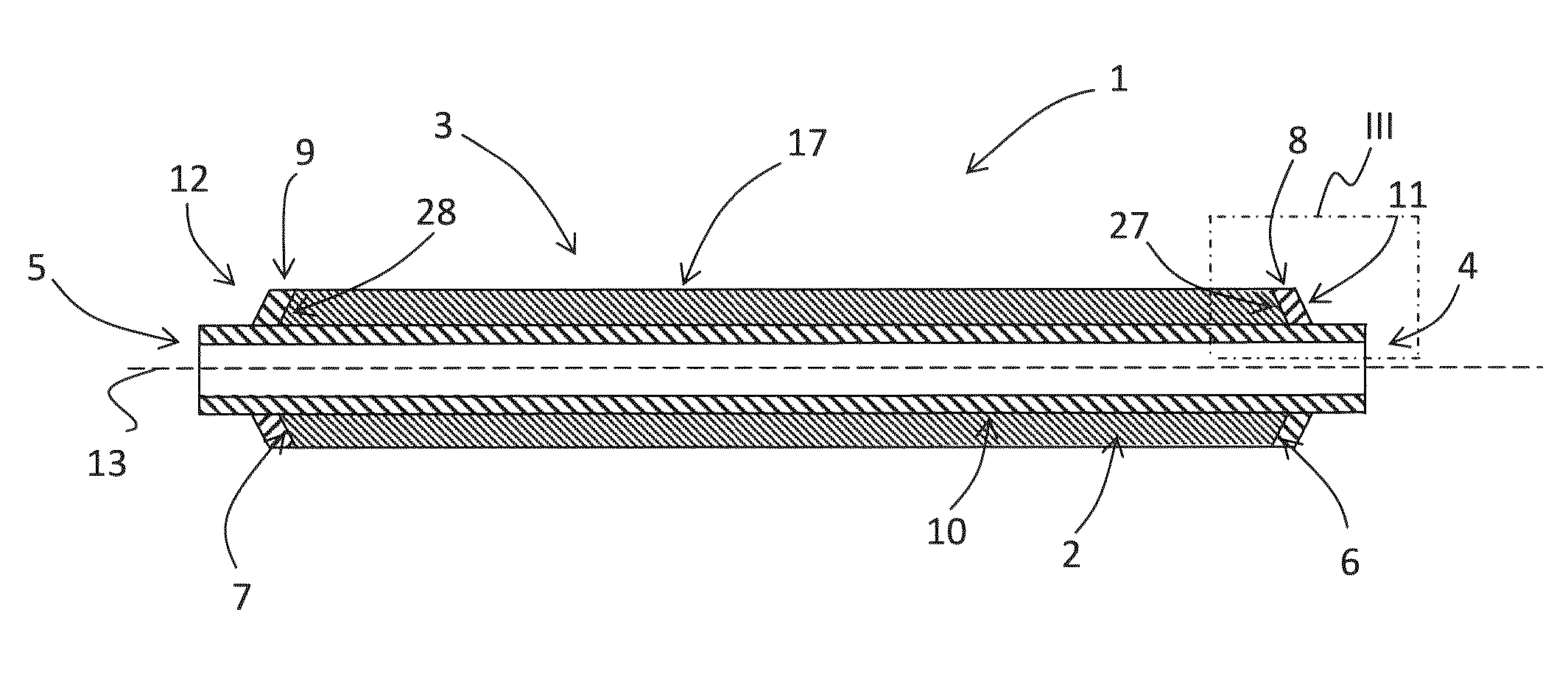
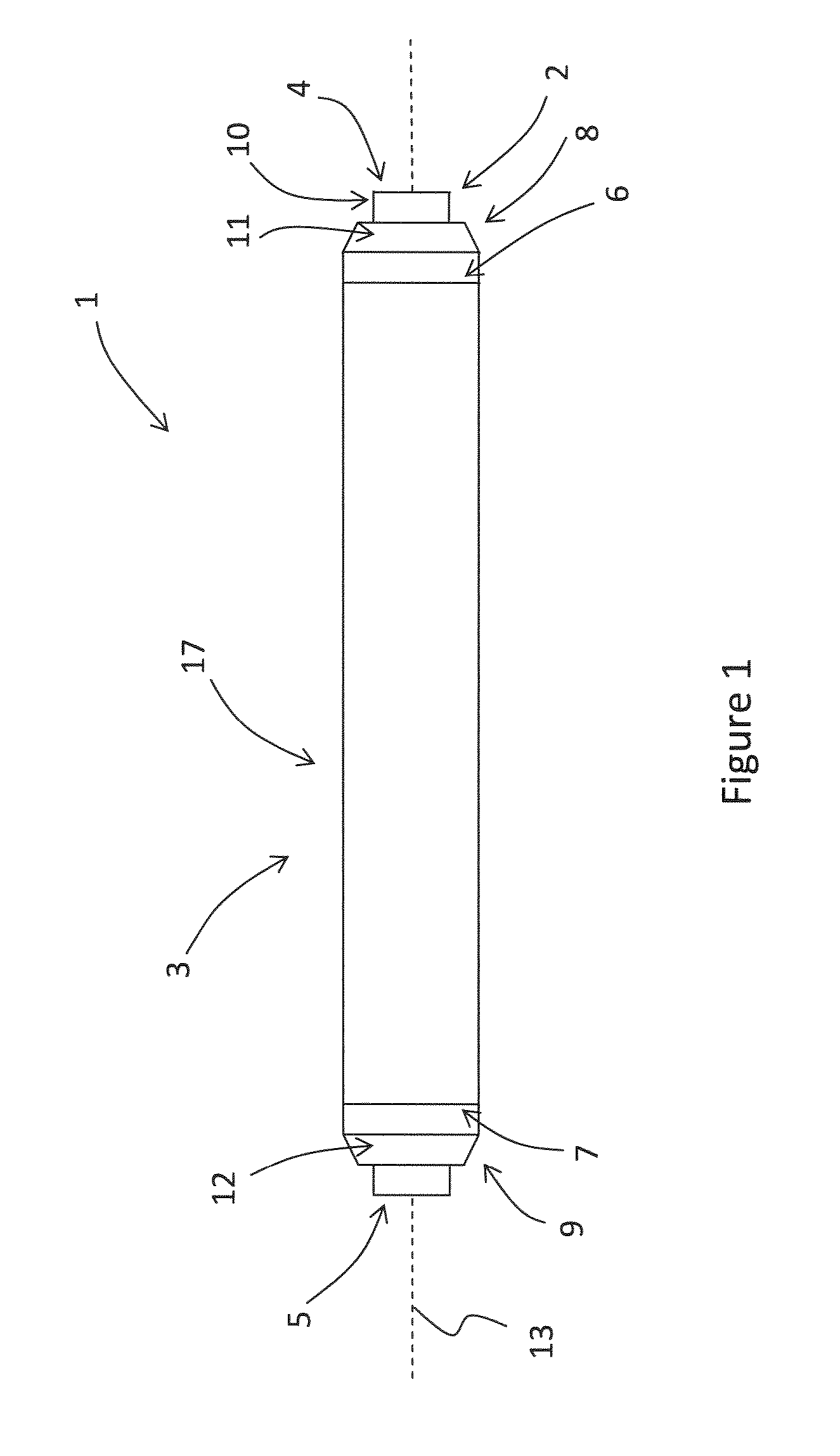
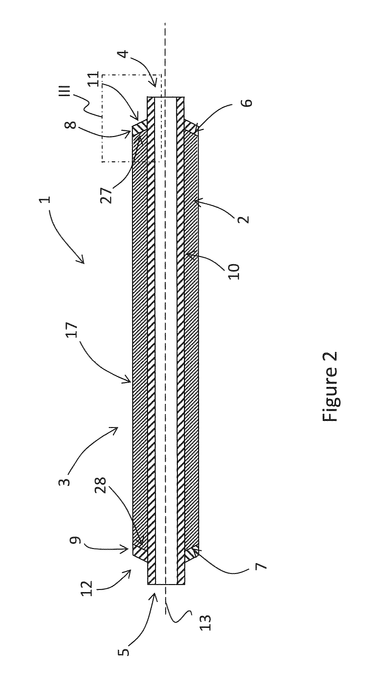
[0084]FIG. 1 shows a side view of an embodiment of the pipeline unit according to the invention. The pipeline unit 1 comprising a pipe member 2 and a pipe coating 3 surrounding the pipe member 2. The pipe member 2 comprises a first pipe end 4 and a second pipe end 5. The pipe coating 3 extends along a length of the pipe member 2 and ends at a first coating end face 6 located at a distance from the first pipe end 4 and at a second coating end face 7 located at a distance from the second pipe end 5. The pipe coating 3 extends along the pipe member 2 from the first coating end face 6 to the second coating end face 7.

[0085]The pipe coating 3 is made from a polyolefin material. A first bonding member 8 made from a polyurethane material is provided on and attached to the first coating end face 6. A second bonding member 9 made from a polyurethane material is provided on and attached to the second coating end face 7. The first bonding member 8 is located at a distance from the first pipe e...


PUM

PropertyMeasurementUnit
temperatureaaaaaaaaaa
thicknessaaaaaaaaaa
thicknessaaaaaaaaaa

Abstract

A pipeline unit (1) comprising a pipe member (2) and a pipe coating (3) surrounding the pipe member (2), which pipe member comprises a pipe end (4), and which pipe coating (3) extends along a length of the pipe member and ends at a coating end face located at a distance from the pipe end, wherein a bonding member (8) is provided on the coating end face, which bonding member (8) is attached to the coating end face and made from a material which is different from the material of which the pipe coating (3) is made.

Description

[0001]This application is the National Stage of International Application No. PCT / NL2012 / 050755, filed Oct. 31, 2012, which claims benefit of Netherlands Patent Application No. 2007692, filed Nov. 1, 2011, and which claims benefit of U.S. Provisional Application No. 61 / 553,493, filed Oct. 31, 2011.FIELD OF THE INVENTION[0002]The present invention relates to a pipeline unit, an assembly of two pipeline units and a method of producing an assembly of two pipeline units.DISCUSSION OF THE PRIOR ART[0003]Pipelines are used in the oil and gas industry for the transportation of hydrocarbons. When hydrocarbon deposits are found under the sea floor, pipelines are often laid on the sea floor for transporting the hydrocarbons to a storage or production facility.[0004]Pipelines are typically formed from many pipeline units that are welded end-to-end before they are laid. Pipeline units comprise a pipe member which are often manufactured from carbon steel and are prone to corrosion if they are no...

Claims


Application Information

Patent Timeline
Patent Type & Authority Patents(United States)
IPC IPC(8): F16L9/14F16L58/18F16L13/02F16L59/20
CPCF16L58/181F16L59/20F16L13/0272F16L9/14Y10T29/49826F16L13/02F16L58/18
Inventor KARYADI, ERWANBOYD, HELEN ROSEBALDER, THOMASVAN ROSENDAAL, SIMONE
Owner HEEREMA MARINE CONTRACTORS NEDERLAND SE
Why Eureka
Try Eureka