
High efficiency hybrid illumination system

a hybrid illumination and high efficiency technology, applied in the field of high efficiency hybrid illumination systems, can solve the problems of high cost and environmental hazards, cfls cannot be easily configured to produce beams of light, and the theoretical superiority of lumens per etendue unit has not been effectively utilized

Active Publication Date: 2016-05-03
FLASCK RICHARD ARTHUR
View PDF28 Cites 7 Cited by
  • Summary
  • Abstract
  • Description
  • Claims
  • Application Information

AI Technical Summary

Benefits of technology

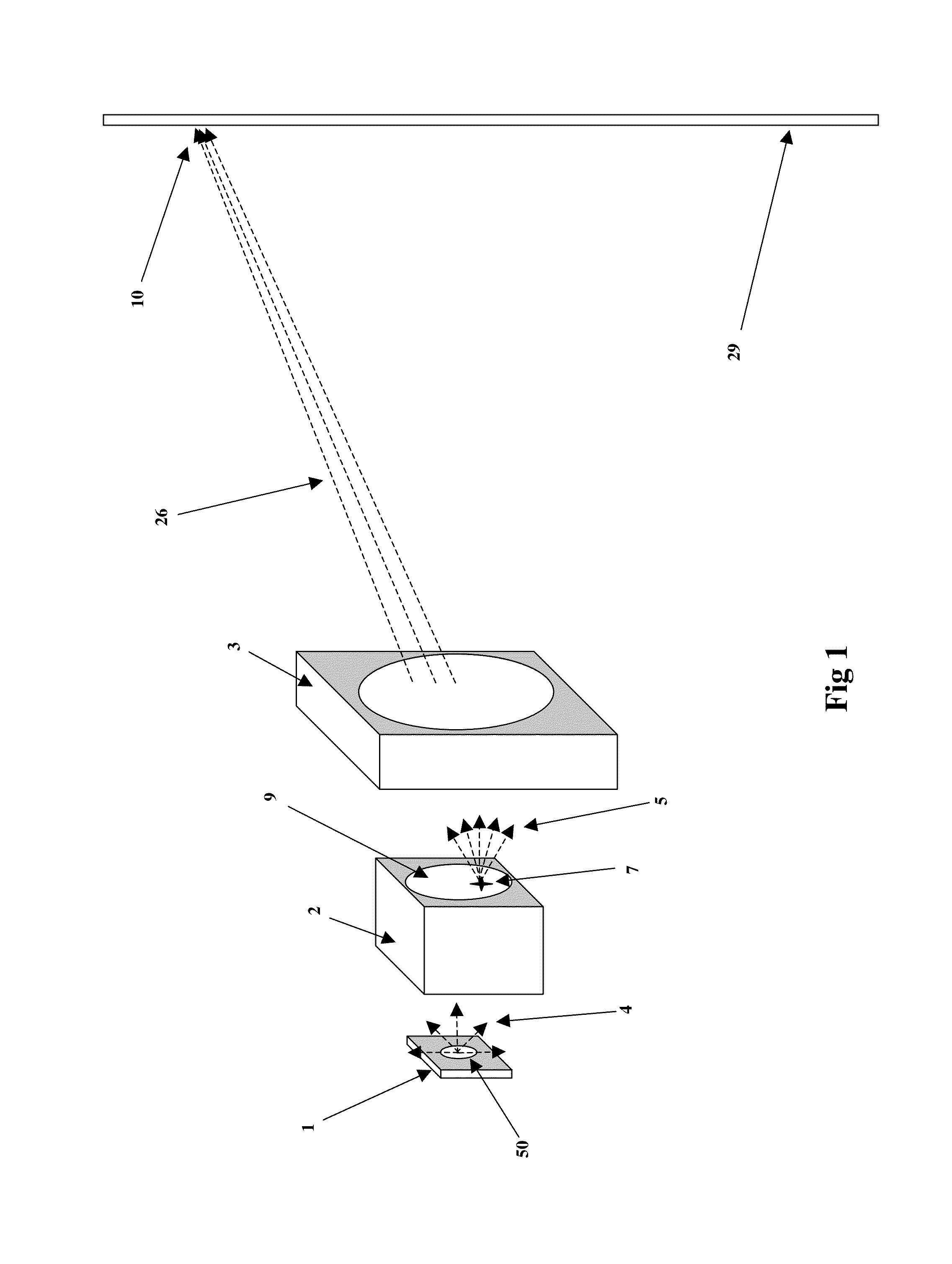
The invention is a hybrid illumination system that has high efficiency in collecting and transforming light from LED chips. It has controlled distribution of light for general illumination and specialty markets, including theatrical and stage lighting. The system has low cost, high brightness, low power consumption, small size, and environmental friendly characteristics. It can output light with brightness, color, fading, and strobing control. It can also be used for floodlights, spotlights, and other luminaires with controllable output characteristics such as brightness, color, and beam angle. The system includes a planar light source, non-imaging optics, and imaging optics. The non-imaging optics have at least two stages that capture and transform the light from the source. The intensity profile of the transformed light is modified using the second stage without significant light loss. The system can produce a soft-edged or bell shaped profile by increasing or decreasing the distance between the output port of the non-imaging optics and the projection optics.

Problems solved by technology

While CFLs have better efficiency and efficacy than filament lamps, they suffer from high cost and environmental hazards.
Also CFLs cannot easily be configured to produce beams of light because the etendue is large and the value of lumens per etendue unit is low.
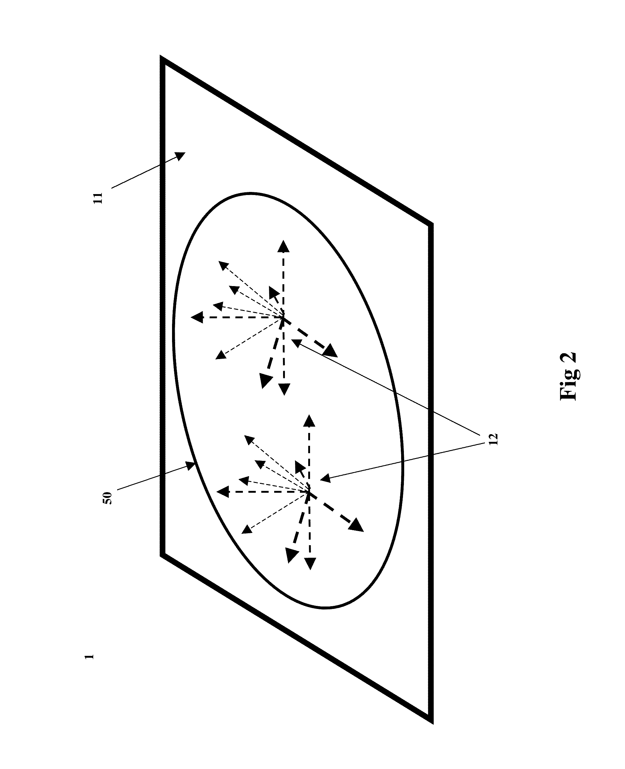
However, in beam forming applications the LED / SSL theoretical superiority in lumens per etendue unit has not been effectively utilized because of the difficulty of designing beam producing optics to accommodate the LED chip hemispherical Lambertian intensity distribution while producing the desired intensity profile in the target area (usually bell shaped or uniform).
This difficulty has been especially true for lighting fixtures (luminaires, and stage lighting instruments or lanterns) that generate beams of light.

Method used


Image

  • High efficiency hybrid illumination system
  • High efficiency hybrid illumination system
  • High efficiency hybrid illumination system

Examples


embodiment

Preferred Embodiment

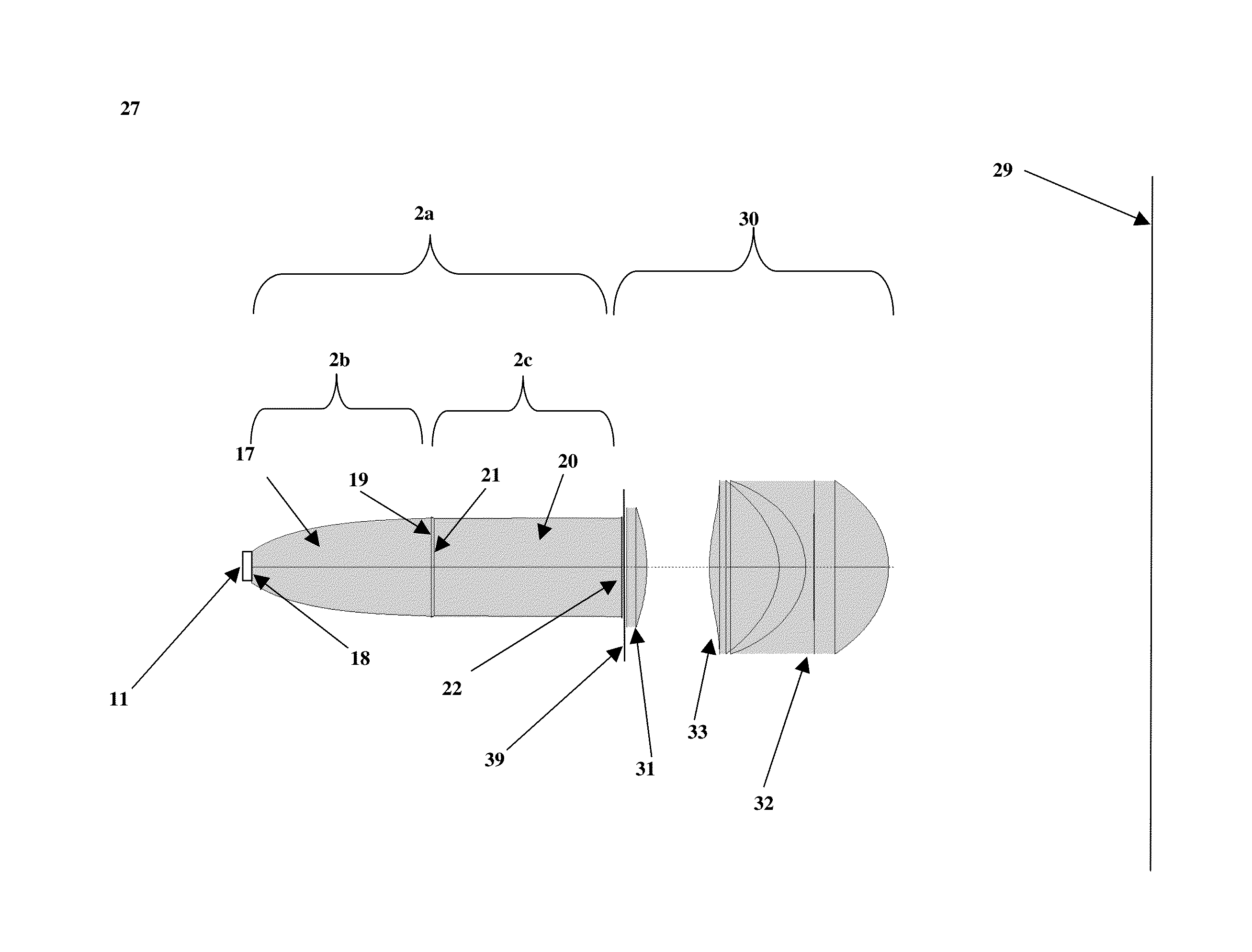
[0054]FIG. 12 shows the hybrid optics illumination system 27 of the Preferred Embodiment. FIG. 12 shows a Lambertian emitter 11 comprising a warm white LED array, a NIO transform means 2a comprising a CPC first stage 17 and a cylindrical second stage 20, and a IO projection optics means comprising lens elements 31, 32, and 33. The optical prescription of this Preferred Embodiment is given in Table 1 in BEAM4 commercial lens design software format.

[0055]

TABLE 113IndexMCSZA2A3A4A5A6D---------------e--------e------------------E-------------e--------e-------e------E---------E--------PMMAM  1.915E−01  4.633E−02−6.115E+00  2.557E−02−4.435E−031.122E−04−3.973E−07−1.144E−0850.6PMMATIR  1.000E+12−2.292E−05−5.000E+0349.652PMMAL  0.000E+00  1.855E+0250.81I  0.000E+00  1.855E+0250.81L  0.000E+00  1.856E+0250.81L  1.880E+0260PMMAL−1.143E−02  1.980E+02601L  6.632E−02−9.934E−02  2.294E+02−2.759E−02  4.779E−0587PMMAL−1.628E−02  1.186E+00  2.644E+02−6.100E−03  4.555E−05871L−2.161E...


PUM


Abstract

Principles of nonimaging optics, imaging optics, etendue matching, and the Constant Brightness Theorem are used to provide an ultra-efficient solid state lighting optical system for stage and theatrical profile spotlights. Used in combination, an array of high brightness light emitting diodes, a nonimaging optical transform element, and an image forming optical element enable the design of profile spotlights capable of high brightness, low electrical power consumption, sharp gobo imaging, adjustable beam intensity profiles, and use of current industry standard accessories and elements, such as gobos, blades and irises.

Description

CROSS-REFERENCE TO RELATED APPLICATIONS[0001]This patent application claims the priority date of provisional patent application No. 61 / 633,852.BACKGROUND OF THE INVENTION[0002]Currently, lighting accounts for a substantial percentage of electricity use in both the United States and world-wide. The lighting industry is moving away from low efficiency sources like tungsten filament lamps to Compact Fluorescent Lamps (CFL) and Solid State Lighting (SSL) based on Light Emitting Diodes (LED). While CFLs have better efficiency and efficacy than filament lamps, they suffer from high cost and environmental hazards. Also CFLs cannot easily be configured to produce beams of light because the etendue is large and the value of lumens per etendue unit is low.[0003]LEDs, however, continue to improve in all performance and cost categories. The efficiency, efficacy and lumens per etendue unit for LEDs are all superior to both filament lamps and CFLs. SSL is desirable because of low power consumptio...

Claims


Application Information

Patent Timeline
Patent Type & Authority Patents(United States)
IPC IPC(8): F21V7/06F21V13/04G02B19/00F21V7/00G02B3/00
CPCF21V7/06F21V13/04F21V7/0066G02B19/0028G02B2003/0093F21V5/008F21V7/0091F21W2131/406F21Y2105/10F21Y2115/10F21Y2113/13G02B19/0066
Inventor FLASCK, RICHARD ARTHUR
Owner FLASCK RICHARD ARTHUR
Learn More