Engine exhaust-driven heating device for use in portable surface drying equipment

a heating device and engine technology, applied in the direction of machines/engines, lighting and heating apparatus, furniture, etc., can solve the problems of inability to move or carry, inability to access, and inability to carry out commercial tasks for indefinite periods, so as to reduce atmospheric emissions, improve the effect of drying surface moisture, and reliable and continuous heat sour

Inactive Publication Date: 2016-05-10
GREEN FLAG SURFACE TECH
View PDF1 Cites 0 Cited by
  • Summary
  • Abstract
  • Description
  • Claims
  • Application Information

AI Technical Summary

Benefits of technology

[0006]An engine exhaust-driven heating device made according to this invention generates a high volume, steady stream of hot gas by passing an exhaust stream from a gasoline, propane, natural gas, or combustible fueled internal combustion engine through a catalyst that reduces the atmospheric emissions of the stream and liberates the energy of the pollutants in the stream, and then combining that catalytic-treated air stream with a fresh air stream to further react with remaining pollutants and generate additional heat. The hot gas may be used to dry a variety of surfaces and, when integrated without other components typically found in surface drying equipment, provides an ideal system for use in a variety of moderate- to large-sized portable surface drying equipment. The heating device provides a reliable and continuous heat source and, when integrated into a controlled delivery system, dries the moisture from a surface faster and more effectively than prior art heating devices.
[0007]In a preferred embodiment of the portable heating system, a catalytic chamber which houses at least one catalyst for treating engine emission pollutants is arranged to receive an exhaust gas stream from an engine, preferably being run in a fuel-rich condition. The exhaust gas stream passes through the catalyst, which can be arranged in one or more stages, into a baffled mixing chamber arranged to receive the catalytic-treated exhaust gas stream. The baffled mixing chamber mixes the catalytic-treated exhaust gas stream with an ambient air stream to produce a cleaner and higher temperature mixed gas stream. A distribution chamber is arranged to receive the mixed gas stream and direct it toward a surface to be dried or stripped of an unwanted layer of material.
[0011]passing an engine exhaust gas stream through a catalytic chamber housing at least one catalyst; the catalyst being suitable for reducing a level of undesired pollutants present in the engine exhaust gas stream;
[0014]Objects of this invention include providing a heating device that (1) contains and controls a catalytic reaction of combustible exhaust gases; (2) uses the catalytic-reacted gas as a heat source; (3) uses fewer components and is less complex than prior art devices; (3) is portable and able to integrate into a range of equipment sizes best suited for a user application; (5) is easy to operate and maintain; (6) has minimal environmental impact; (7) is safer than prior art devices; and (8) creates a very cost effective choice relative to prior art surface drying technology.

Problems solved by technology

Any variety of commercial tasks, endeavors or public events can be delayed for indefinite periods of time while waiting for natural evaporation to occur after a moisture-generating event (e.g., dew, mist, rain, frost, snow, plumbing failures).
The disadvantages of drying equipment that makes use of prior art heating devices include (1) lack of mobility or portability and a limited ability to access all surface areas with the heated air stream; (2) safety hazards posed by the device to users and bystanders; (3) complex design with an associated higher operating and maintenance cost; (4) a limited lifespan of the heating source and an inability of the heat source to withstand rough handling and service; (5) a need to be connected to a main source of high amperage electrical power; and (6) limitations on the amount of heated air that can be generated due to the engineering constraints of the materials from which the heating device is constructed.

Method used


Image

  • Engine exhaust-driven heating device for use in portable surface drying equipment
  • Engine exhaust-driven heating device for use in portable surface drying equipment
  • Engine exhaust-driven heating device for use in portable surface drying equipment

Examples


Embodiment Construction

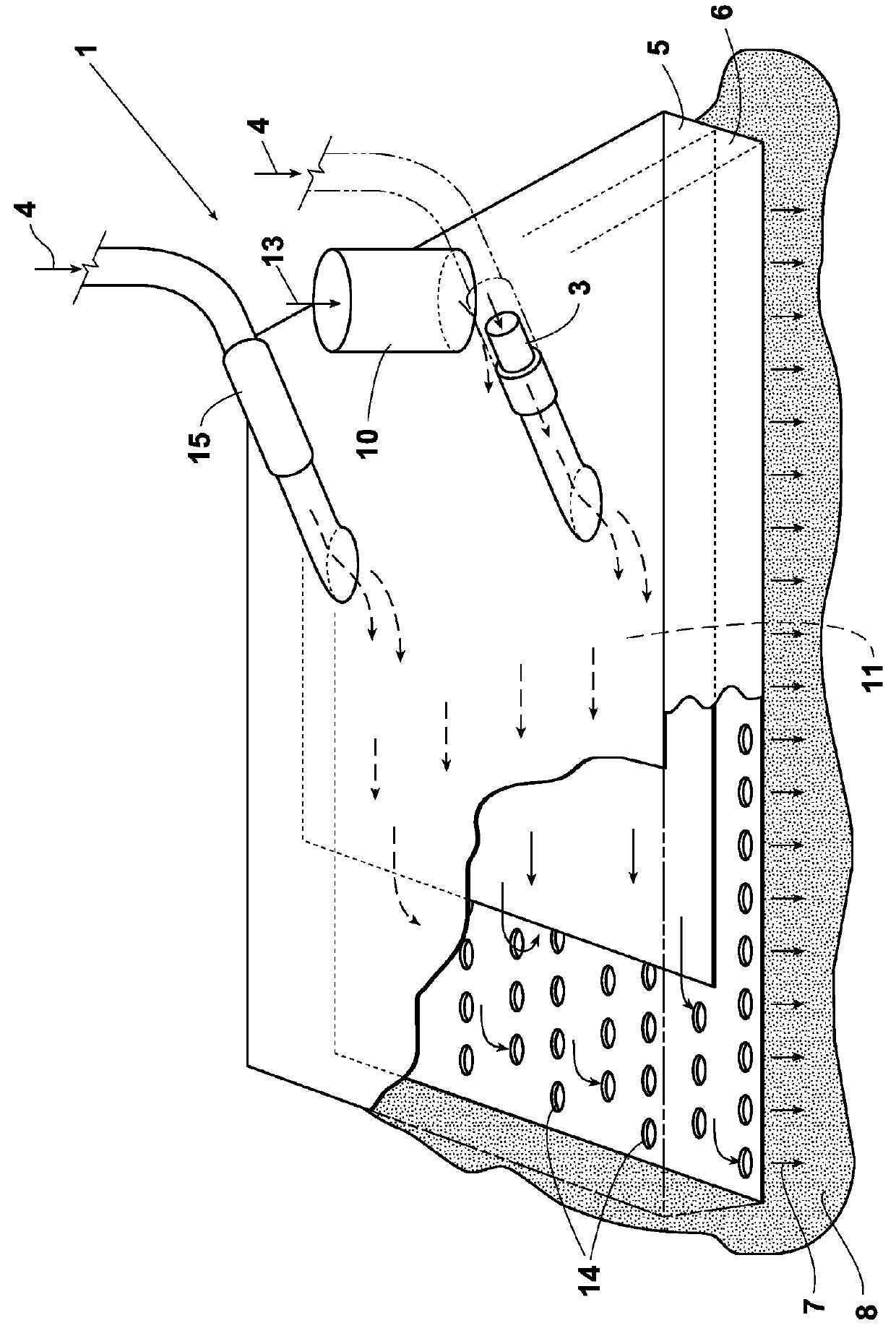
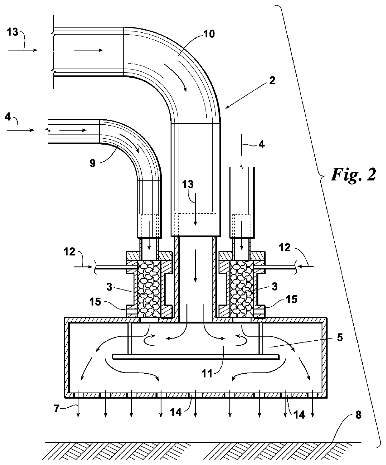
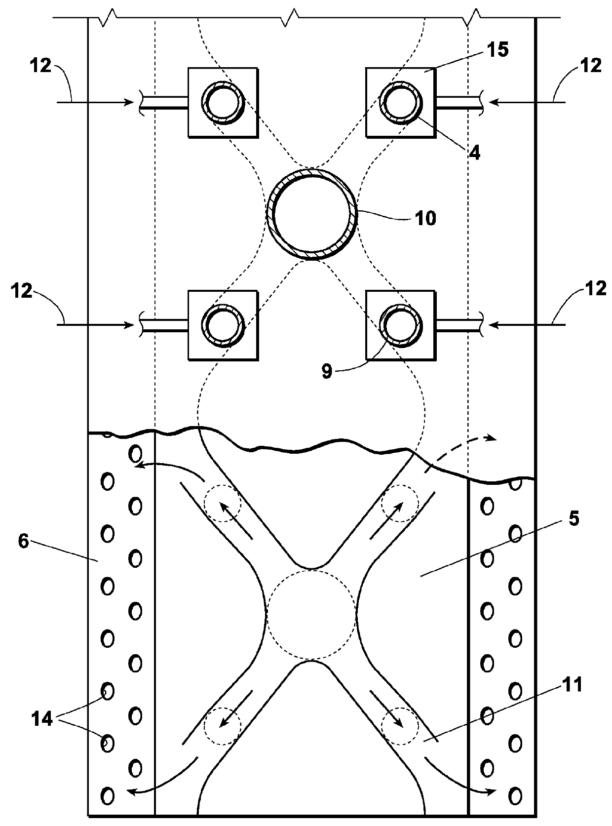
[0033]Referring to FIGS. 1 to 3, preferred embodiments of an engine exhaust-driven heating device include a dual catalytic heater plenum 1 arrangement (see FIG. 1) and a multiple catalytic heater plenum 2 arrangement (see FIGS. 2 & 3). In each embodiment, a catalytic chamber 15, which is in communication with an exhaust piping 9 of an engine (not shown), houses a catalyst 3 through which an exhaust stream 4 is passed. The exhaust stream 4, which is preferably from an air-cooled, gasoline-fueled engine, can be mixed ahead of catalyst 3 with a secondary stream of pressurized air 12 (preferably at approximately 1 psi). An ambient air stream 13 from a blower (not shown) passes through blower tubing 10.

[0034]The two streams—ambient air stream 13 and either catalytic treated exhaust stream 4 or catalytic treated exhaust stream 4 with pressurized air stream 12—meet in baffled mixing chamber 5 as combined stream 11 where additional reaction occurs, breaking down remaining constituents in th...


PUM


Abstract

An engine exhaust-driven heating device generates a high volume, steady stream of hot gas by passing an exhaust stream from a gasoline, propane, natural gas, or combustible fueled internal combustion engine through a catalyst that reduces the atmospheric emissions of the stream and liberates the energy of the pollutants in the stream. The device then combines the catalytic-treated air stream with a fresh air stream to further react with remaining pollutants and generate additional heat. The hot gas may be used to dry a variety of surfaces and, when integrated without other components typically found in surface drying equipment, provides an ideal system for use in a variety of moderate- to large-sized portable surface drying equipment. The heating device provides a reliable and continuous heat source and, when integrated into a controlled delivery system, dries the moisture from a surface faster and more effectively than prior art heating devices.

Description

CROSS-REFERENCE TO CO-PENDING APPLICATIONS[0001]This application claims the benefit of U.S. Prov. Appl. Ser. No. 61 / 971,675 filed Mar. 28, 2014, the content of which is hereby incorporated by reference.BACKGROUND OF THE INVENTION[0002]This invention generally relates to heating devices used in drying equipment. More particularly, the invention relates to heating devices used in drying equipment that make use of an exhaust gas stream from a gasoline, propane, natural gas, or combustible fueled internal combustion engine as a means of generating heat for dissipating and evaporating moisture from a surface.[0003]Any variety of commercial tasks, endeavors or public events can be delayed for indefinite periods of time while waiting for natural evaporation to occur after a moisture-generating event (e.g., dew, mist, rain, frost, snow, plumbing failures).[0004]Prior art drying equipment either extracts moisture from the surface-to-be-dried (see e.g., U.S. Pat. No. 8,281,499 B2) or generate...

Claims


Application Information

Patent Timeline
Patent Type & Authority Patents(United States)
IPC IPC(8): F01N5/02F26B3/02F01N3/10F26B23/00F26B23/02F01N1/08F01N3/28F01N3/30F01N13/08F01N13/00
CPCF26B23/001F01N3/10F01N5/02F26B3/02F01N1/083F01N3/2882F01N3/30F01N13/002F01N13/08F01N2270/04F01N2270/10F01N2590/06F26B23/024F26B19/005F26B21/001F26B21/004F26B23/02
Inventor BRUSH, ROBERTROBINSON, JR., JOHN W.
Owner GREEN FLAG SURFACE TECH
Why Eureka
Try Eureka