Device and method for low-carbon synergistic utilization of extracting gas with high and low concentrations

A low-concentration gas and gas extraction technology, which is applied in the field of low-carbon synergistic utilization of high- and low-concentration gas extraction devices, can solve the problems of high cost and low-concentration gas not being fully utilized, so as to achieve recycling and reduce the greenhouse effect. , the effect of low-cost capture

Inactive Publication Date: 2021-12-03
CHINA UNIV OF MINING & TECH
View PDF8 Cites 0 Cited by
  • Summary
  • Abstract
  • Description
  • Claims
  • Application Information

AI Technical Summary

Problems solved by technology

[0007] The above patents realize the combustion and utilization of high and low concentration gas, but do not involve the emission of CO after gas combustion 2 capture function, and the cost is relatively high, and low-concentration gas has not been fully utilized

Method used


Image

  • Device and method for low-carbon synergistic utilization of extracting gas with high and low concentrations
  • Device and method for low-carbon synergistic utilization of extracting gas with high and low concentrations
  • Device and method for low-carbon synergistic utilization of extracting gas with high and low concentrations

Examples


Embodiment 1

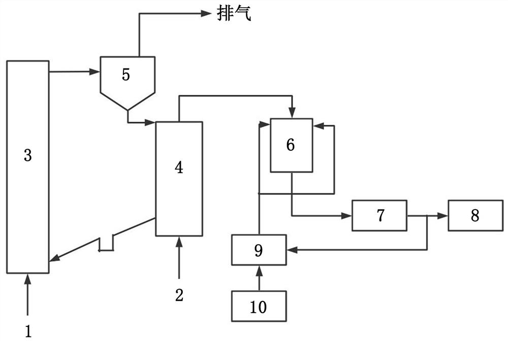
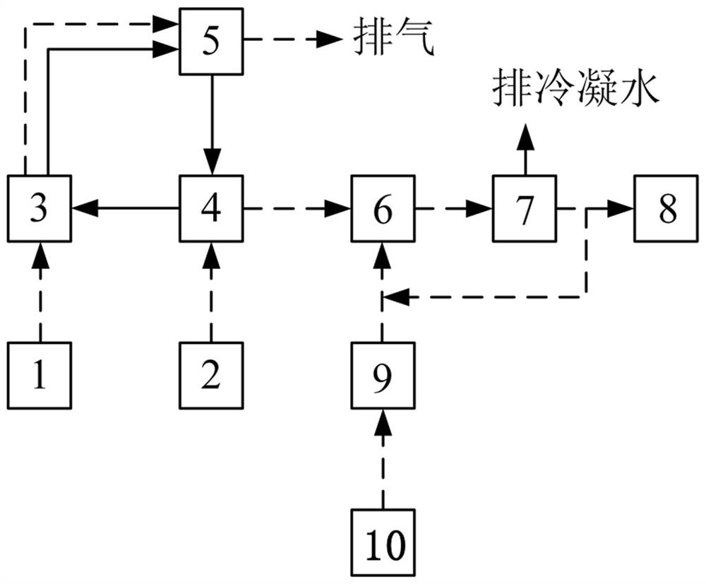
[0046] A device for low-carbon synergistic utilization of high and low concentration gas drainage, see figure 1 and figure 2 , including low-concentration gas 1, high-concentration gas 2, oxygen carrier, air reactor 3, fuel reactor 4, gas-solid separator 5, pure oxygen supplementary combustion device 6, condensing device 7, CO 2 Capture device 8, premixed gas distribution system 9 and air separation unit 10, described fuel reactor 4 comprises the fuel reactor main body that is provided with heating device, the oxygen carrier inlet that is located at the top edge of fuel reactor main body, is located at The gas outlet at the top center of the fuel reactor body, the oxygen carrier outlet at the bottom of the side wall of the fuel reactor body, the high-concentration gas inlet at the bottom of the fuel reactor body, the gas distribution plate at the bottom of the fuel reactor body and The solid feed port located on the side wall of the main body of the fuel reactor and above th...

Embodiment 2

[0049] Same as Example 1, the difference is that the pipeline connecting the air reactor 3 and the gas-solid separator 5, the pipeline connecting the combustion chamber and the pure oxygen supplementary combustion device 6, and the pipeline connected between the pure oxygen supplementary combustion device 6 and the condensing device 7 Both have combustible gas CH 4 、H 2 , CO and O 2 A sensor probe and a temperature-measuring thermocouple, the sensor probe and the temperature-measuring thermocouple are connected to a PLC control system to monitor and control the state and temperature of the gas in the pipeline through the PLC control system.

[0050] The pipeline connecting the air reactor 3 and the fuel reactor 4 is provided with a particle circulation control device and an isolator, and the particle circulation control device and the isolator are used to assist in sending fluidization wind to the side of the air reactor 3 to prevent gas And the particles flow back from the ...

Embodiment 3

[0092] With embodiment 2, the difference is that the preparation method of the oxygen carrier is as follows: the micron Fe 2 o 3 with nanoscale Al 2 o 3 The particles are mixed according to the mass ratio of 1:1 and put into a beaker filled with an equal amount of deionized water. After stirring evenly at a speed of 200r / min, the sample is placed in a drying oven and kept at a constant temperature of 100°C until the water is completely evaporated; Place the dried sample in a muffle furnace, and set the muffle furnace calcination program as follows: at a heating rate of ≤5°C / min, from room temperature to 650°C, and then at a heating rate of ≤2°C / min, from 650°C to 650°C Raise the temperature from ℃ to 1000℃, keep it at 1000℃ for 120min, then cool down from 1000℃ to 650℃ at a cooling rate of ≤2℃ / min, and finally cool down from 650℃ to room temperature at a cooling rate of ≤5℃ / min; use The calcined sample is crushed and sieved by a small crusher, and particles with a particle ...


PUM

PropertyMeasurementUnit
particle diameteraaaaaaaaaa

Abstract

The invention relates to a device and method for low-carbon synergistic utilization of extracting gas with high and low concentrations. The method comprises the following steps of introducing the high-concentration gas into a fuel reactor, and enabling the high-concentration gas to react with an oxygen carrier in the fuel reactor to reduce the oxygen carrier; feeding the reduced oxygen carrier into an air reactor, simultaneously feeding the low-concentration gas to react with the reduced oxygen carrier to oxidize the oxygen carrier, feeding the oxidized oxygen carrier into a gas-solid separator under the driving of the low-concentration gas, emptying the gas separated by the gas-solid separator, and feeding the solid oxygen carrier into a combustion reactor; and feeding flue gas generated in the combustion reactor into a pure oxygen afterburning device, meanwhile, introducing mixing gas of a premixing gas distribution system for mixing pure oxygen prepared by an air separation device and CO2 condensed by a condensing device into the pure oxygen afterburning device, so that the flue gas is fully combusted, enabling combustion gas to enter the condensing device to be condensed, feeding the condensed CO2 into a CO2 trapping device, and discharging condensed water. According to the device and the method, not only is the energy utilization of the gas realized, but also the CO2 can be captured at low cost.

Description

technical field [0001] The invention relates to the technical field of coal mine production, in particular to a device and method for low-carbon coordinated utilization of high- and low-concentration gas drainage. Background technique [0002] Coalbed methane, commonly known as "gas", is a hydrocarbon gas that coexists with coal, and its main component is CH 4 . In the process of coal mine production, due to different extraction methods and discharge locations, CH in coalbed methane 4 The content of CH is quite different, such as the CH in goaf and pressure relief coal seam gas 4 The concentration is usually 30~95%, and the CH in exhaust gas (also called ventilation gas) 4 The concentration is not even 1%. where CH 4 The part with a concentration higher than 30% can be effectively utilized by conventional combustion technologies, such as gas power generation, gas boilers, alumina roasting, and coal slime drying. On the other hand, the explosion limit of methane is 5%...

Claims


Application Information

Patent Timeline
Patent Type & Authority Applications(China)
IPC IPC(8): F23G7/07C01B32/50
CPCF23G7/07C01B32/50F23G2209/14
Inventor 刘方宋晨杨丽宋正昶翟成赵江源吴鑫亢炜燎贾志轩
Owner CHINA UNIV OF MINING & TECH
Why Eureka
Try Eureka