Developing device and image forming apparatus

a technology of developing device and image forming apparatus, which is applied in the direction of electrographic process apparatus, instruments, optics, etc., can solve the problems of new problems and the risk of splashing of the developer inside the apparatus, and achieve the effect of suppressing the occurrence of agglomerates and high image quality

Active Publication Date: 2016-05-10
CANON KK
View PDF17 Cites 5 Cited by
  • Summary
  • Abstract
  • Description
  • Claims
  • Application Information

AI Technical Summary

Benefits of technology

[0020]The present invention suppresses occurrence of agglomerates and maintains a high image quality in a developing device having a plurality of developer bearing members.

Problems solved by technology

In addition, when the coating amount of the second developing sleeve 128 is greater than the appropriate value, an overflow of the developer from the developing container 122 occurs and there is a risk of splashing of the developer inside the apparatus.
However, in FIG. 10, when the regulating member 130 is provided, new problems occur as follows.

Method used


Image

  • Developing device and image forming apparatus
  • Developing device and image forming apparatus
  • Developing device and image forming apparatus

Examples


embodiment

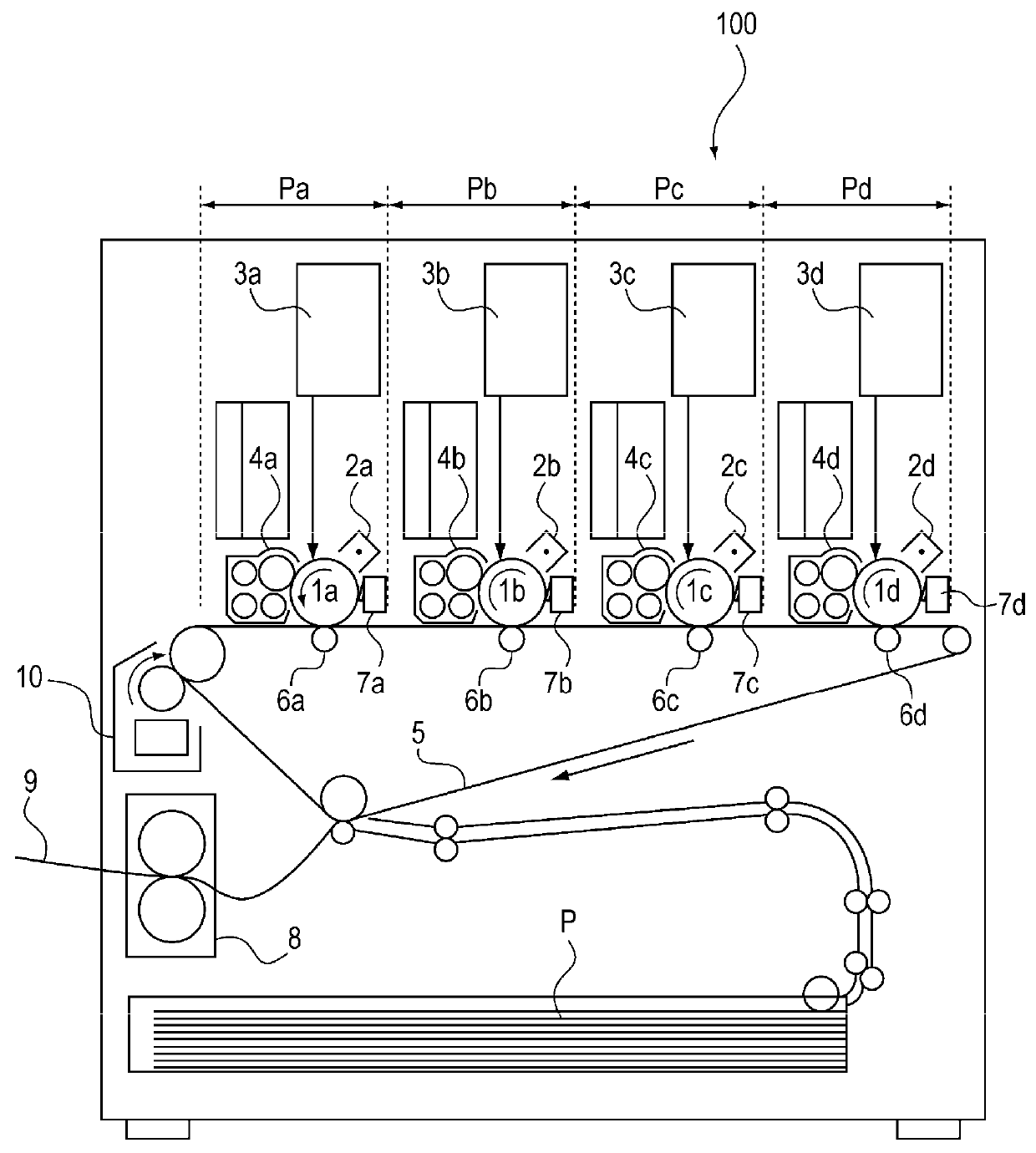
[0038]An embodiment of the present invention will be explained in detail with reference to the figures. FIG. 1 is an overall explanatory view of an image forming apparatus of this embodiment.

[0039](Image forming apparatus) As shown in FIG. 1, the image forming apparatus 100 is a full color printer of the tandem type intermediate transfer system and along the intermediate transfer belt 5 the image forming apparatus 100 has four image forming units P (Pa, Pb, Pc and Pd) which form a color toner image.

[0040]A toner image of yellow is formed in the image forming unit Pa, the toner image of magenta is formed in the image forming unit Pb, the toner image of cyan is formed in the image forming unit Pc and a toner image of black is formed in the image forming unit Pd.

[0041]As shown in FIG. 1, the photosensitive drums 1 (1a, 1b, 1c, 1d) as image bearing members on which toner images are borne and the process means for them are disposed in the image forming units P (Pa, Pb, Pc and Pd). Becaus...

example 1

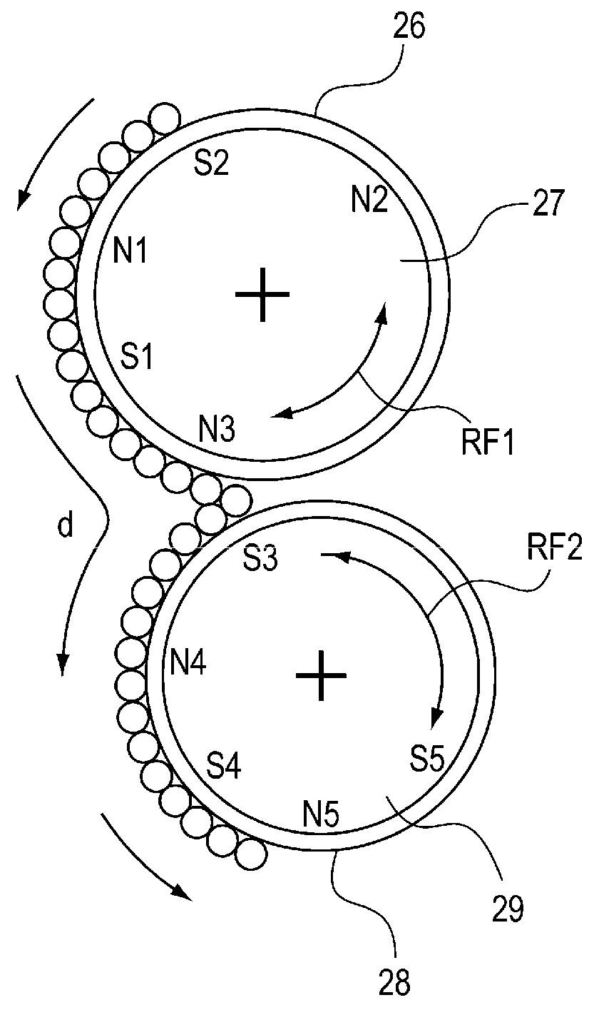
[0099]The structures of the first magnet roller 27 which is included in the upstream developing sleeve 26 and the second magnet roller 29 which is included in the downstream developing sleeve 28 will be explained in detail. FIG. 7 is a diagram illustrating the configuration of the Example 1 according to the present embodiment.

[0100]At the centers of the first magnet roller 27 and the second magnet roller 29, the shaft 27a and the shaft 29a of the round shaft are provided as a rotation axis. In this example, the magnet rollers have five magnetic poles. Thus, in order to form five poles of the magnetic pole N2 (scooping pole), the magnetic pole S2, the magnetic pole N1, the magnetic pole S1 and the magnetic pole N3 (delivery pole) around the shaft, five magnet pieces are bonded at positions corresponding to magnetic poles respectively. Although five magnetic poles and five the magnet pieces are used in this example, the invention is not limited to this.

[0101]In this example, the shaft...

example 2

[0122]The example 2 will be described with reference to FIG. 8. FIG. 8 is a diagram illustrating the configuration of the example 2 according to the present embodiment.

[0123]In Example 1, a magnetic pattern having the effect of the present embodiment is created by utilizing the fact that magnetic force of the same polarity as the repulsion poles is generated between the repulsion poles by placing a magnetic pole with opposite polarity of repulsion poles which have high magnetic force at the back side of the area between the repulsion poles.

[0124]With the configuration of the Example 1, the effect can be obtained with a simple structure. However, the arrangement of the magnetic poles must be determined by the various factors including the positional relationship between the photosensitive drum 1 and the developing container 22 and effect on image quality. Thus, the arrangement of the Example 1 cannot always be realized.

[0125]As a countermeasure for this case, in this example, the mag...


PUM


Abstract

A developing device includes a first magnet fixed inside a first developer bearing member and including a pair of first repulsion magnetic poles with the same polarity and disposed adjacent to each other, and a second magnet fixed inside a second developer bearing member and including a pair of second repulsion magnetic poles with the same polarity and disposed adjacent to each other. The first magnet has a magnetic flux density distribution of a normal component of the first developer bearing member in the circumferential direction of the first developer bearing member having only one minimal point between the pair of first repulsion magnetic poles, and the second magnet has a magnetic flux density distribution of a normal component of the second developer bearing member in the circumferential direction of the second developer bearing member having a plurality of minimal points between the pair of second repulsion magnetic poles.

Description

BACKGROUND OF THE INVENTION[0001]1. Field of the Invention[0002]The present invention relates to a developing apparatus which performs development using an electrophotographic system and which has a plurality of the developer bearing members, and to an image forming apparatus using the developing apparatus.[0003]2. Description of the Related Art[0004]As an image forming apparatus such as an electrophotographic copying machine, a developing device using a magnetic brush method of two-component developing method is known. Also, a method of development in which one developing sleeve (developer bearing member) is used for one photosensitive drum (image bearing member) is generalized.[0005]However, in the recent demand of high-speed to a copying machine, when the speed of the rotational movement of the photosensitive drum becomes faster, a preferable image is not necessarily formed with only one developing sleeve.[0006]Thus, there is a developing device in which a plurality of developing...

Claims


Application Information

Patent Timeline
Patent Type & Authority Patents(United States)
IPC IPC(8): G03G15/09
CPCG03G15/0921G03G2215/0648
Inventor SAKAMAKI, TOMOYUKI
Owner CANON KK
Why Eureka
Try Eureka