

Systems and methods for implementing advanced vacuum belt transport systems
a technology of advanced vacuum belts and transport systems, applied in the direction of thin material processing, article separation, printing, etc., can solve the problems of inability to accelerate, decelerate, jitter, and affect the image quality of the produced images in the image forming device, so as to reduce or substantially eliminate the impact of frictional forces
- Summary
- Abstract
- Description
- Claims
- Application Information
AI Technical Summary
Benefits of technology
Problems solved by technology
Method used
Image

Examples
Embodiment Construction
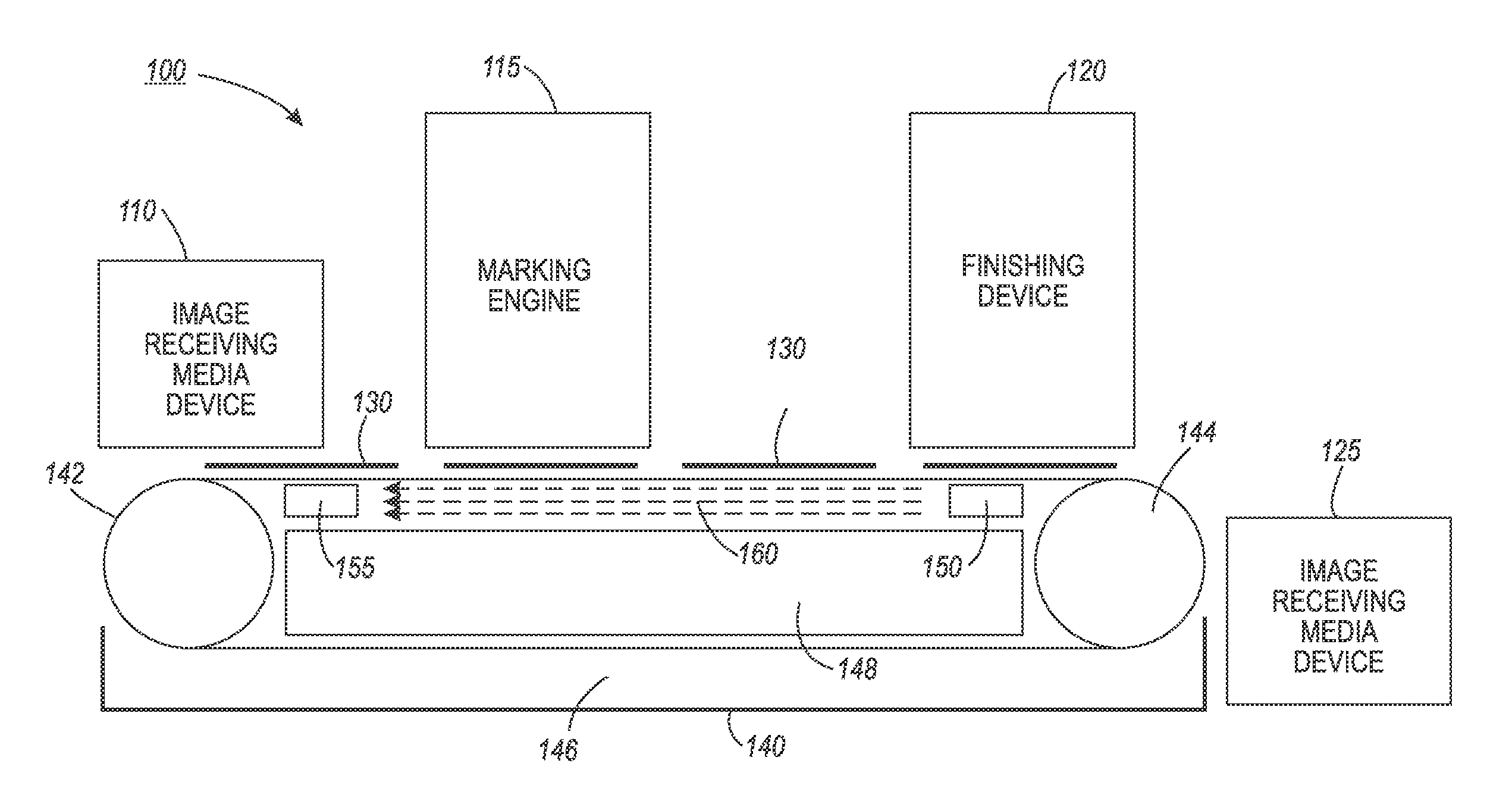
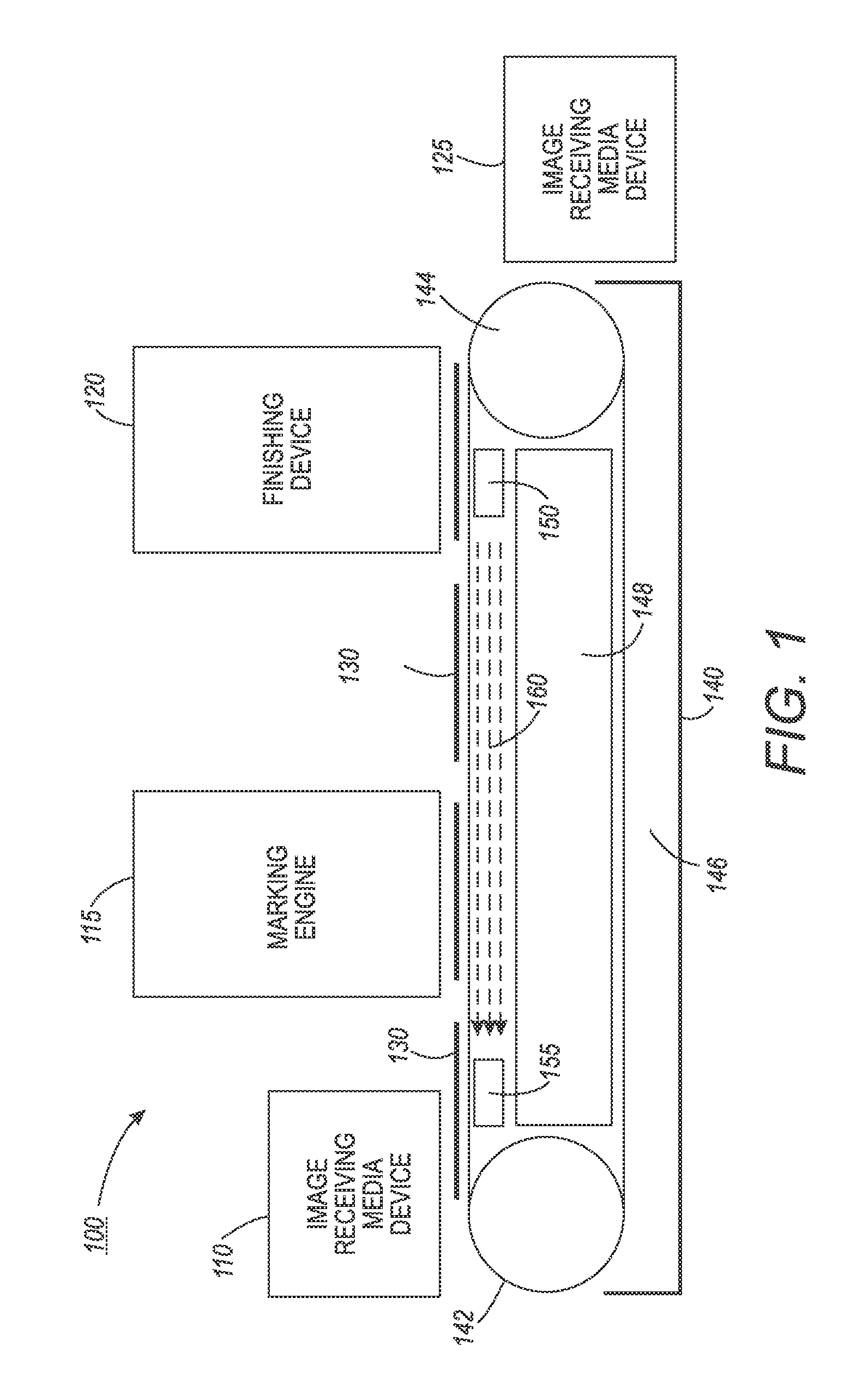
[0002]This disclosure relates to systems and methods for implementing more consistent vacuum belt transport movement for the transport of image receiving media in image forming devices, and for the transport of packages and components for processing and storage in myriad transport belt systems employing vacuum plenums to support and secure the materials being transported on the vacuum belts.
[0003]2. Related Art
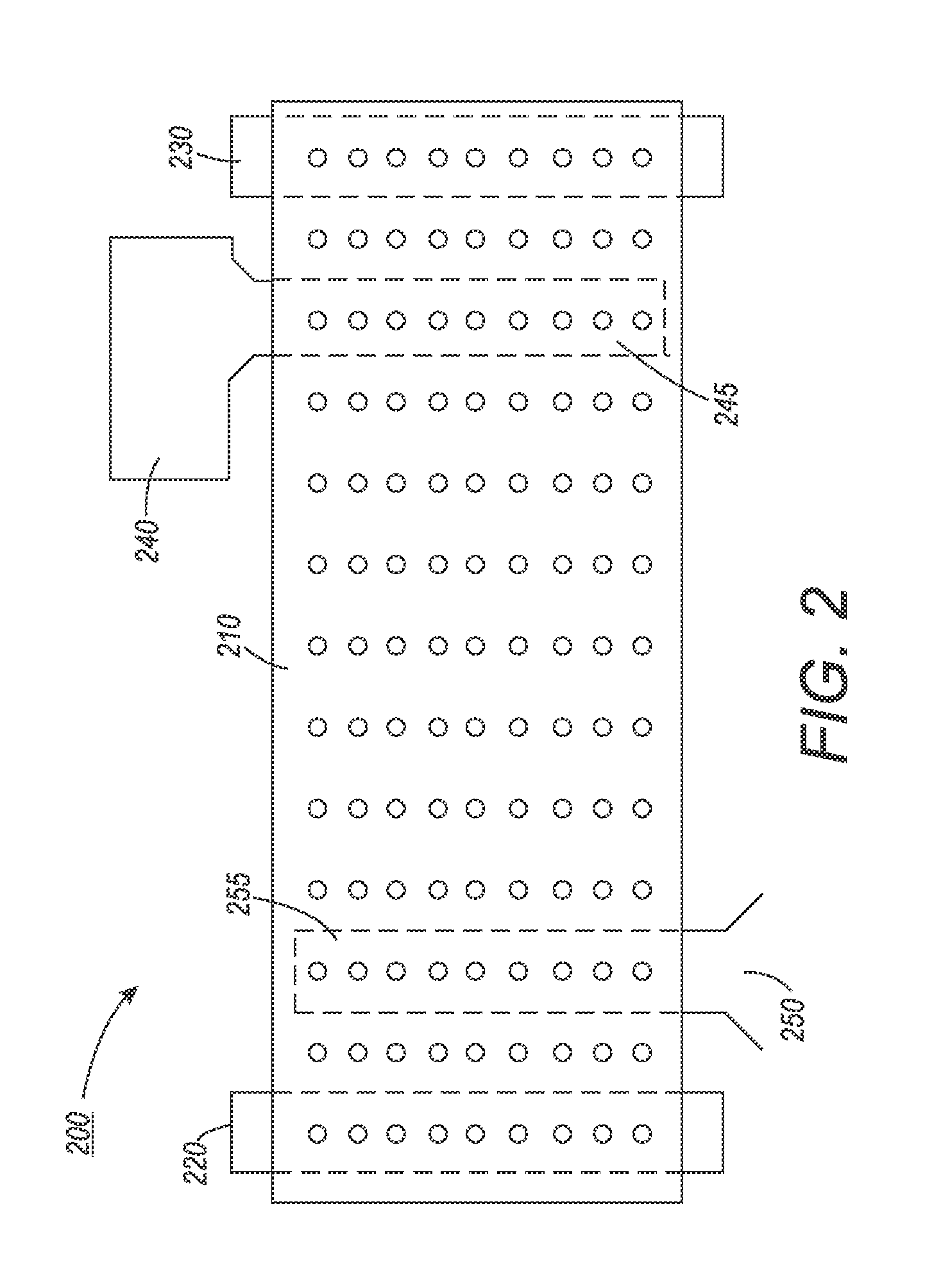
[0004]Many industries use component transport belt systems in order to transport individual packages, components and the like between and through package and / or component processing devices, or within, for example, warehouse structures for storage or delivery. The vacuum belts used in certain vacuum belt transport systems may be perforated with holes that facilitate the application of a vacuum pressure from one or more vacuum plenums located beneath the vacuum belt over at least a portion of the transport path traversed by the vacuum belt in the vacuum belt transport system. S...
PUM
 Abstract
Description
Claims
Application Information