
Reduced bandwith of signal in an envelope path for envelope tracking system

a signal bandwith and tracking system technology, applied in the field of envelope tracking systems, can solve the problems of sub-nanosecond timing alignment accuracy, difficult to achieve and maintain b>106/b> for these higher bandwidth systems, and extremely difficult to design a supply modulator with a bandwidth greater than 40 mhz using existing semiconductor technology

Active Publication Date: 2016-05-24
SNAPTRACK
View PDF17 Cites 1 Cited by
  • Summary
  • Abstract
  • Description
  • Claims
  • Application Information

AI Technical Summary

Benefits of technology

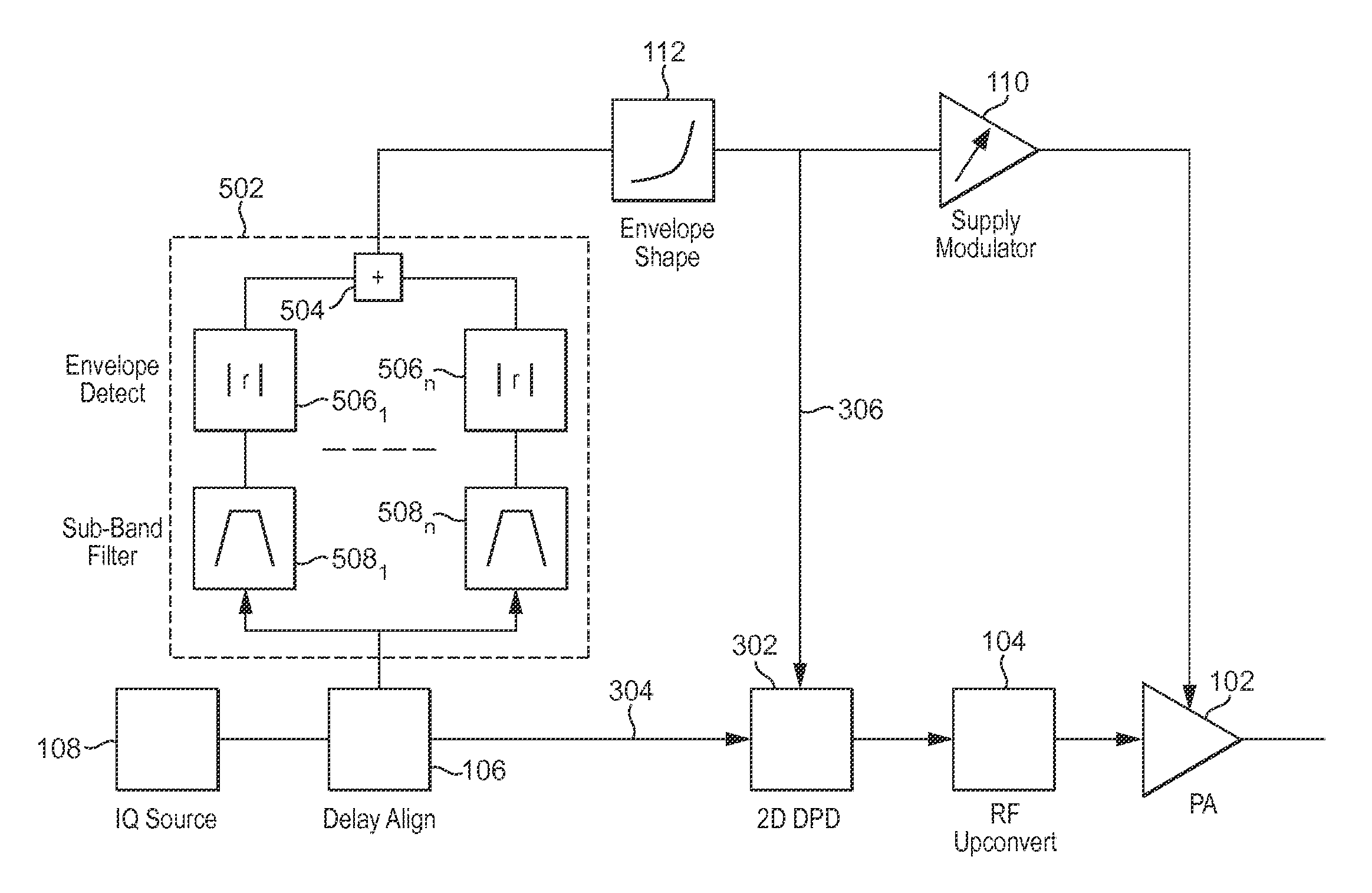
The invention provides an envelope tracking power amplifier system that includes an RF input path and an envelope path. The envelope path includes multiple envelope detectors that detect the envelope of a plurality of frequency bands of an input signal and generate output signals. These output signals are combined using a combiner to create a composite envelope signal. The system also includes a digital pre-distortion block that receives the input signal and the power amplifier supply voltage and provides an input to a modulator that supplies power to the RF amplifier. The system further includes a delay block that aligns the power amplifier supply voltage and the power amplifier input voltage. The invention provides an improved method for amplifying signals in a more efficient and effective way.

Problems solved by technology

The design of a supply modulator having a bandwidth of greater than 40 MHz is extremely challenging using existing semiconductor technology.
Furthermore, the sub-nanosecond timing alignment accuracy which is required to be controlled by the delay block 106 for these higher bandwidth systems becomes increasingly difficult to achieve and maintain.
It then is not possible to linearise the RF signal using RF pre-distortion due to excessive power amplifier compression.

Method used


Image

  • Reduced bandwith of signal in an envelope path for envelope tracking system
  • Reduced bandwith of signal in an envelope path for envelope tracking system
  • Reduced bandwith of signal in an envelope path for envelope tracking system

Examples


Embodiment Construction

[0044]The present invention is now described by way of reference to preferred examples and preferred implementations. However one skilled in the art will appreciate that the present invention is not limited to its application to the specific examples as set out hereinbelow.

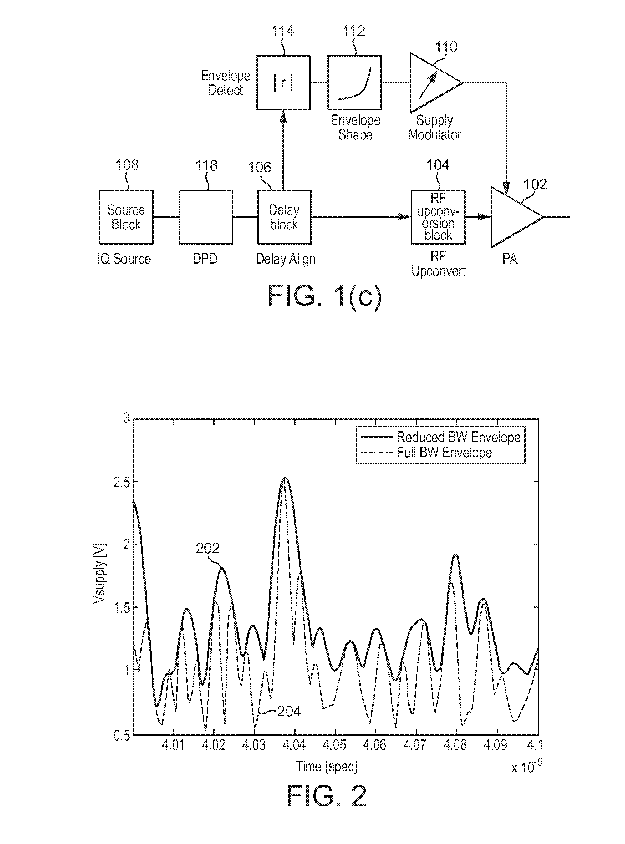
[0045]It is possible to correct for the non-linearity resulting from the envelope path bandwidth reduction by using a two-dimensional DPD block, which applies pre-distortion which depends on both the instantaneous RF envelope of the RF input signal and the instantaneous supply voltage. A two-dimensional DPD block receives a signal representing the instantaneous supply input to the power amplifier and a signal representing the signal input to the power amplifier.

[0046]An implementation of an envelope tracking power amplifier system incorporating a two-dimensional DPD block is illustrated in FIG. 3. In the system of FIG. 3 like reference numerals are used to identify similar elements to earlier figures. As illustrat...


PUM


Abstract

An envelope tracking power amplifier system comprising an RF input path and an envelope path for providing a modulated power amplifier supply, further comprising a plurality of envelope detectors for detecting the envelope of a plurality of frequency bands of an input signal and each generating an output signal, and a combiner for combining the output of the envelope detectors.

Description

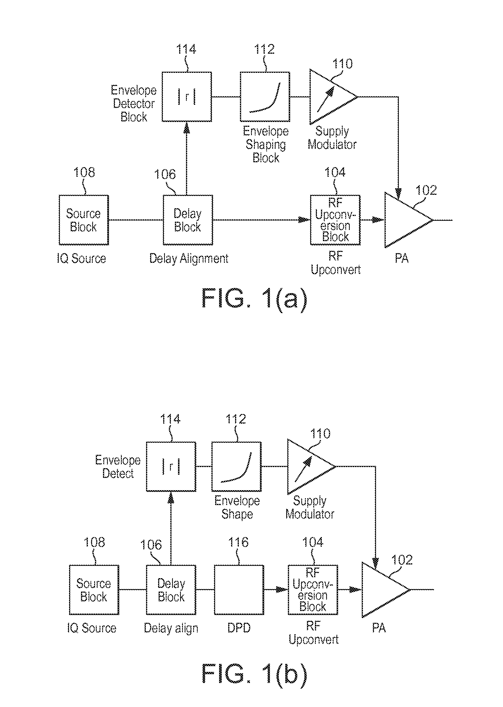
CROSS-REFERENCE TO RELATED APPLICATION(S)[0001]Great Britain Patent Application No. 1318524.4, with a filing date of Oct. 21, 2013, is incorporated herein by reference.FIELD OF THE INVENTION[0002]The present invention relates to envelope tracking systems having an RF input path to a signal input of a power amplifier and an envelope path to a supply input of a power amplifier. Such envelope tracking systems may be utilised in cellular systems or WiFi systems for example.BACKGROUND TO THE INVENTION[0003]Envelope tracking power amplifier systems are known in the art, and generally comprise the provision of an input signal to be amplified on an RF input path to a signal input of a power amplifier, and an envelope path for generating a modulated power supply based on the input signal, with the modulated power supply being provided to a power supply input of the power amplifier.[0004]An exemplary prior art envelope tracking power amplifier system is illustrated in FIG. 1(a). A signal to b...

Claims


Application Information

Patent Timeline
Patent Type & Authority Patents(United States)
IPC IPC(8): H03G3/20H03F3/24H03F3/189H03F3/00H03F1/32H03F1/02H03F1/30H03F3/21H03F3/04
CPCH03F1/30H03F1/0227H03F1/3241H03F3/005H03F3/189H03F3/21H03F3/211H03F3/245H03F2200/102H03F2200/111H03F2201/3206H03F2203/21181H03F2203/21184H03F2203/21193H03F1/0222H03F1/3294
Inventor WIMPENNY, GERARD
Owner SNAPTRACK
Learn More