Drive device for a self-propelled machine and corresponding method

a self-propelled machine and drive device technology, which is applied in the direction of fluid gearings, fluid gearings, gearing elements, etc., can solve the problems of high installation space requirements of the drive device, high manufacturing cost, and inability to change the shift state only in standstill, so as to achieve short-time compensation, compact design, and reliable transmission of high torque of the second hydraulic motor.

Active Publication Date: 2016-05-31
NAF NEUNKIRCHENER ACHSENFABRIK
View PDF14 Cites 1 Cited by
  • Summary
  • Abstract
  • Description
  • Claims
  • Application Information

AI Technical Summary

Benefits of technology

[0030]In an advantageous development of the invention, it is provided that upon shifting the coupling device from the second into the first shift state, toothings of the synchronizing body and the gear wheel corresponding with each other are engaged with each other and / or that upon shifting the coupling device from the first into the second shift state, the toothings of the synchronizing body and the gear wheel corresponding with each other are disengaged from each other. In other words, it is provided that the synchronizing body and the gear wheel are additionally coupled to each other via a form-fit connection at least upon established frictional fit in the first shift state of the coupling device. Hereby, particularly high torques of the second hydraulic motor can be reliably transmitted. As the toothing, for example, a so-called pre-toothing can be used on the synchronizing body and / or gear wheel. A further advantage is in that the friction surfaces of the synchronizing body and the gear wheel are predominantly required only for short-time compensation for possible rotation speed differences. Therefore, the synchronizing body and the gear wheel can be particularly compactly designed. Thus, the advantages of a conventional toothing (form-fit connection, independent of pressure) are combined with those of a multi-disk clutch (engaging / disengaging even under load).
[0031]Further advantages arise if the coupling device includes a shift cylinder, by means of which the synchronizing body and the gear wheel are moved relatively to each other. Hereby, simple shifting of the coupling device between the first and the second shift state is allowed. With the aid of the shift cylinder, therein, the synchronizing body and the gear wheel are moved relatively to each other. Basically, the shift cylinder can be mechanically, electrically, pneumatically, magnetically and / or hydraulically operated.
[0032]In a further advantageous development of the invention, it is provided that the coupling device accelerates the second hydraulic motor at least to a preset minimum rotation speed upon shifting from the second shift state into the first shift state, preferably before establishing the frictional fit between the synchronizing body and the gear wheel. Hereby, the friction power arising upon engaging the second hydraulic motor is advantageously reduced. This is in particular advantageous if the second hydraulic motor is to be coupled to the moved gear wheel from the rest, since by the short-time swiveling out of the second hydraulic motor, the launch torque thereof does not or not alone have to be overcome by the friction pairing of synchronizing body-gear wheel.

Problems solved by technology

However, the operating range of a hydraulic motor usually does not allow covering the entire drive range of the work machines from maximum traction force at small speeds up to the maximum traveling speed.
Due to the greater gear ratio, however, the second hydraulic motor reaches its rotation speed limit already at relatively low speed and therefore has to be decoupled at larger speeds.
However, the change of the shift states is only possible in standstill in many drive devices.
However, the circumstance is to be considered disadvantageous in such a drive device that both hydraulic motors have to obtain an own hydraulic drive determined by the system.
This results in a correspondingly high installation space requirement of the drive device as well as in high manufacturing costs.
However, this requires a comparatively large dimensioning of the multi-disk clutch, whereby the installation space requirement and the manufacturing costs of the drive device in turn significantly increase.

Method used


Image

  • Drive device for a self-propelled machine and corresponding method
  • Drive device for a self-propelled machine and corresponding method
  • Drive device for a self-propelled machine and corresponding method

Examples


Embodiment Construction

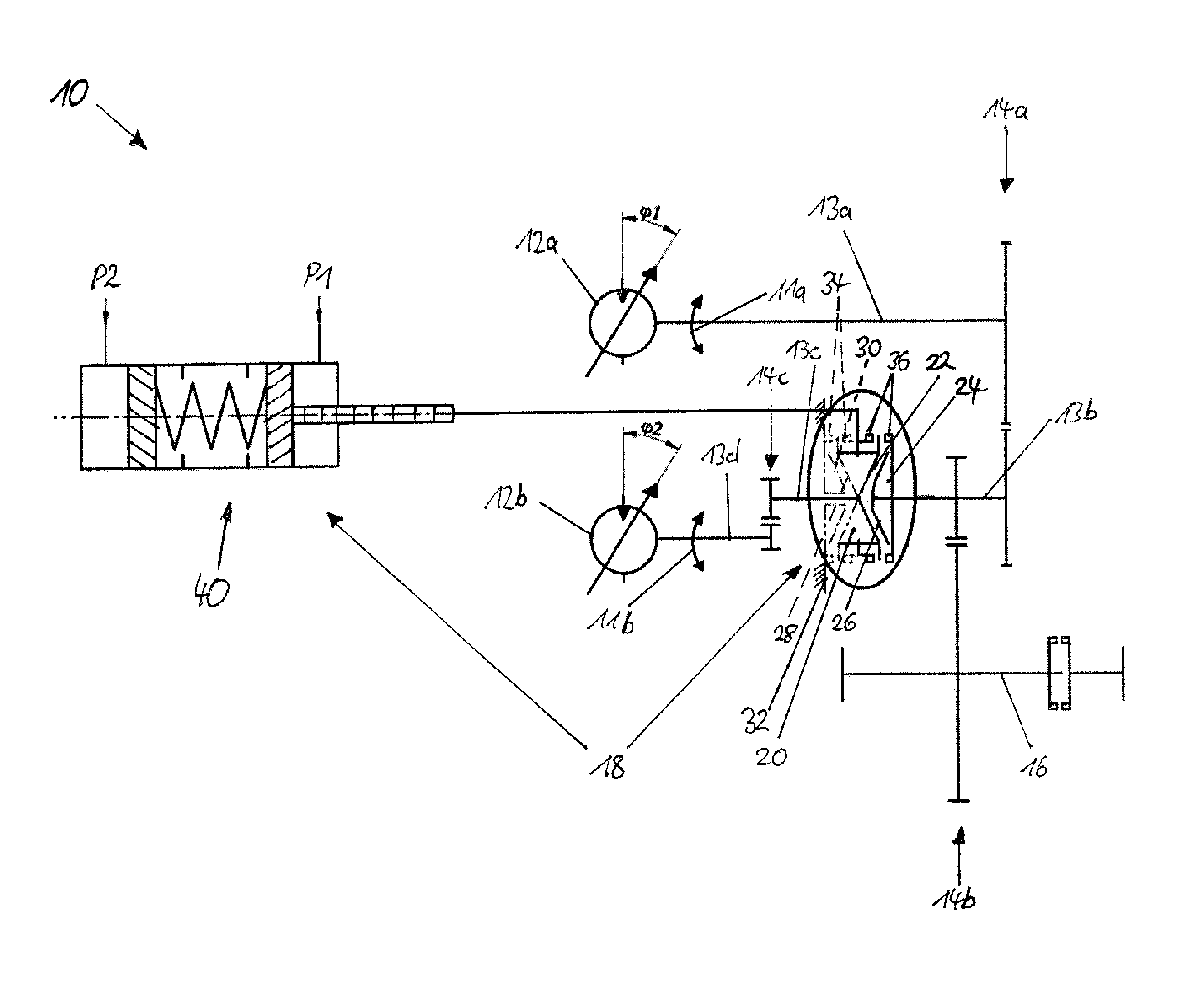
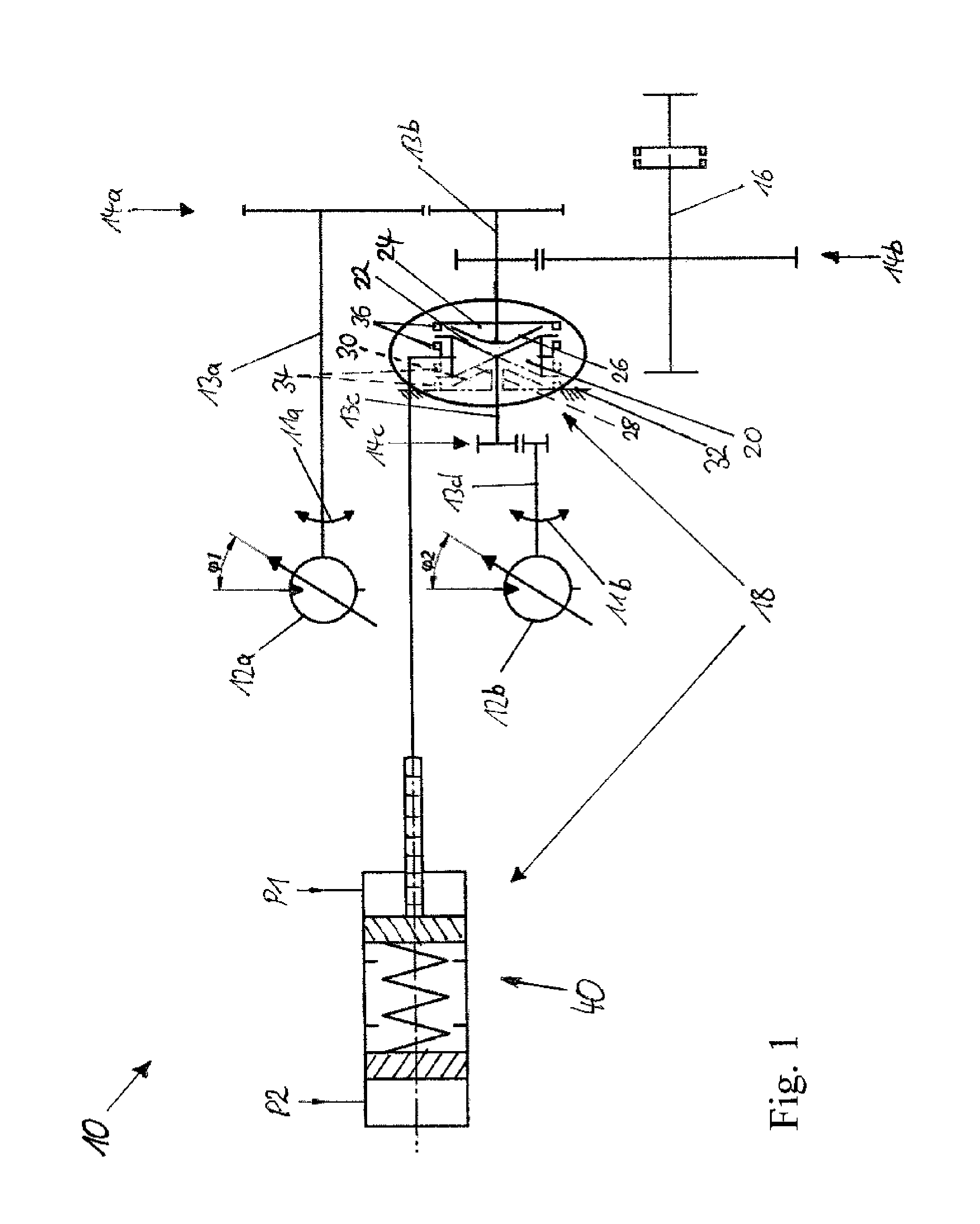
[0037]FIG. 1 shows a schematic illustration of a drive device 10 according to the invention for a land-based, automotive work machine (not shown). The drive device 10 includes a first hydraulic motor 12a, which is drivable by means of hydraulic fluid and is coupled to a driven shaft 16 via a shaft 13a, a gear pairing 14a, a shaft 13b and a gear pairing 14b. Furthermore, the drive device 10 includes a second hydraulic motor 12b drivable by means of hydraulic fluid and a coupling device 18, by means of which the second hydraulic motor 12b can be coupled to the driven shaft 16 for torque addition in a first shift state and can be decoupled from the driven shaft 16 in a second shift state. The hydraulic motor 12a has a working range, which does not allow covering the entire drive range of the work machine of high traction force at small traveling speeds up to very high traveling speeds. Therefore, the first hydraulic motor 12a is provided for fast speeds and lower traction forces and pe...


PUM


Abstract

The invention relates to a drive device (10) for an automotive work machine, wherein the drive device (10) includes a first hydraulic motor (12a) coupled to a driven shaft (16), a second hydraulic motor (12b) and a coupling device (18), by means of which the second hydraulic motor (12b) can be coupled to the driven shaft (16) for torque addition in a first shift state, and can be decoupled from the driven shaft (16) in a second shift state. The coupling device (18) in turn includes at least one synchronizing body (20) with a conical friction surface (22) coupled to the second hydraulic motor (12b) and a gear wheel (24) with a corresponding friction surface (26) movable relatively to the synchronizing body (20) and coupled to the driven shaft (16).

Description

BACKGROUND OF THE INVENTION[0001]The invention relates to a drive device of the type specified in the preamble of claim 1 for an automotive work machine. The invention further relates to an automotive work machine with a drive device as well as to a method for operating a drive device of an automotive work machine.[0002]Conventional drive devices for mobile work machines are driven by hydraulic motors. However, the operating range of a hydraulic motor usually does not allow covering the entire drive range of the work machines from maximum traction force at small speeds up to the maximum traveling speed. Therefore, conventional drive devices have two shift states, the first shift state of which with greater gear ratio is adapted for slow speeds and large traction forces and the second shift state of which with lower gear ratio is adapted for fast speeds and lower traction forces. Therein, a hydraulic motor usually remains permanently engaged with constant gear ratio and covers the en...

Claims


Application Information

Patent Timeline
Patent Type & Authority Patents(United States)
IPC IPC(8): F16H37/06F16H47/02F16H61/30F15B15/14
CPCF16H37/065F16H47/02F16H61/30F15B15/1409F16H2047/025F16H2061/307Y10T74/19014
Inventor SCHNABEL, BERNHARD
Owner NAF NEUNKIRCHENER ACHSENFABRIK
Why Eureka
Try Eureka