Unitized phase over phase two-way or three-way high voltage switch assembly with one vacuum interrupter per phase

a high-voltage switch and vacuum interrupter technology, which is applied in the direction of air-break switches, high-tension/heavy-dress switches, electrical equipment, etc., can solve the problems of special long expensive transmission poles and time-consuming, and achieve the effect of reducing the minimum required distance between phases

Active Publication Date: 2016-05-31
CLEAVELANDPRICE ENTERPRISES
View PDF9 Cites 6 Cited by
  • Summary
  • Abstract
  • Description
  • Claims
  • Application Information

AI Technical Summary

Benefits of technology

[0007]The untized phase over phase two-way or three-way switch assembly of the present invention solves the problems of the prior art arrangement. The two-way or three-way switch assembly of the present invention is a phase over phase arrangement which, in the case of a three-way assembly, includes three arrays of three-way switches, i.e., three switches per phase, pre-mounted on a beam, one array for each phase. The beam in the operative position is vertical and attached to a vertical transmission pole. The cylindrically-shaped insulators of the present invention are cantilevered in such a manner that their axes extend axially horizontally in a cantilevered fashion from the vertical transmission pole, as opposed to the prior art arrangement with all the switch insulators being vertically oriented with their axes, vertically arranged, parallel to the vertical transmission pole. The unitized three phase three-way switch assembly is fully factory adjusted before being shipped to the job site. This arrangement of switches being pre-mounted on a beam for installation on a utility pole in a phase over phase arrangement is called a untized switch arrangement. The switches of the present invention for each phase are driven by a “push-pull” mechanical linkage instead of the prior art purely torsional drive which have so-called “wind-up” problems because of the length of pipe used to engage the switches. Together with a single power interrupter the array of three-switches for each phase forms a switching unit that is mounted to the beam without the need of the previously mentioned prior art support braces for the triangular bracket, for example, thereby reducing the minimum required distance between phases for a particular voltage switch assembly.

Problems solved by technology

Traditionally such switch gear assemblies in a two-way or three-way switch configuration with one vacuum interrupter per phase in a three phase system have had problems with phase over phase spacing for a given voltage requiring special long expensive transmission poles.
Also, with such three-way switches when installing the switches it is very time consuming because each phase has to be installed separately and the mechanical operating mechanism between the phases is field installed and adjusted.

Method used


Image

  • Unitized phase over phase two-way or three-way high voltage switch assembly with one vacuum interrupter per phase
  • Unitized phase over phase two-way or three-way high voltage switch assembly with one vacuum interrupter per phase
  • Unitized phase over phase two-way or three-way high voltage switch assembly with one vacuum interrupter per phase

Examples


Embodiment Construction

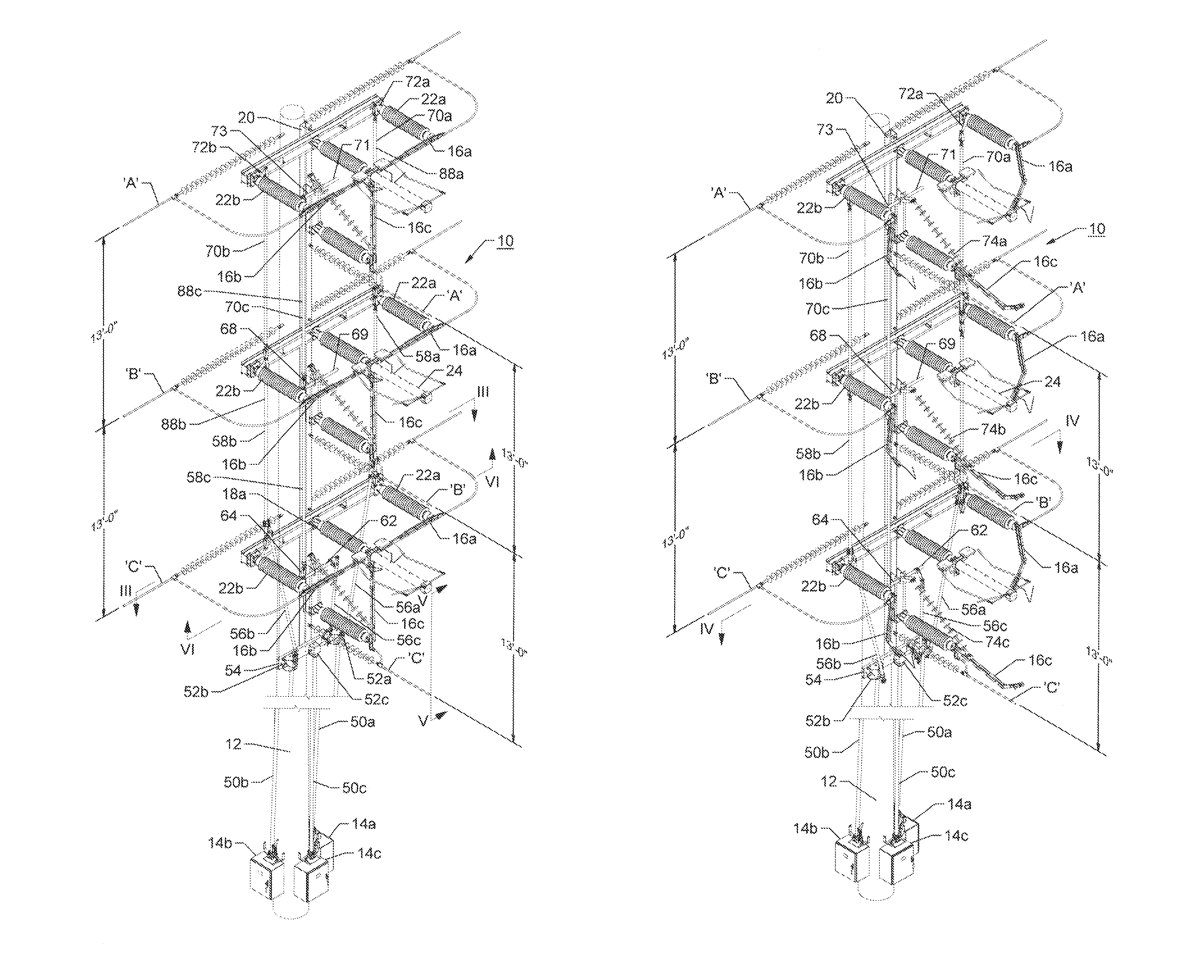
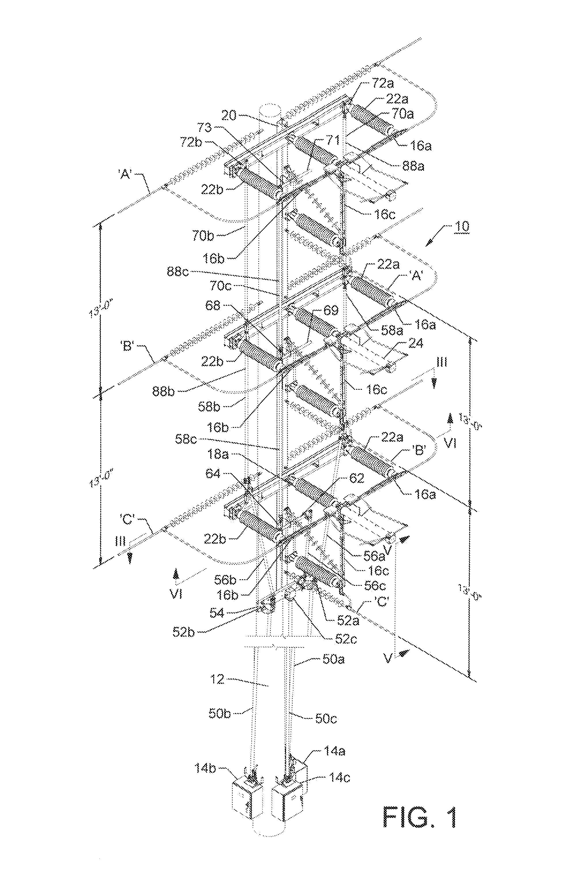
[0017]FIG. 1 shows a unitized phase over phase high voltage 3-way high voltage switch assembly 10 mounted to an electric utility vertical pole 12 which typically is concrete or steel. The switch assembly 10 can handle voltages of, for example, 69 kV (thousand volts) to 161 kV with current carrying capacity of 1200 amperes to 2000 amperes. The switch assembly 10 is adapted to be engageable with a three phase alternating current electrical power system which includes an upper phase ‘A’, an intermediate phase ‘B’ and a lowest phase ‘C’. The phase over phase 3-way switch assembly is typically operatively attached and engageable with three motor operators 14a, 14b, and 14c. The motor operators 14a, 14b, 14c may be such as sold by Cleaveland / Price Inc., the present assignee, as motor operator model no. TPC. More details of the attachment of the motor operators 14a, 14b, 14c to respective switches will be described subsequently.

[0018]Each of the three phases ‘A’, ‘B’ and ‘C’ has three swit...


PUM


Abstract

Switch gear for interconnecting a plurality of power transmission lines including a number of high voltage switches arranged in three phases for routing power in multiple directions. The switches are pre-mounted on a beam to form a three phase unit as a unitized assembly which is attached in the field to a vertical support structure. Each phase includes a vertical break switch and two side break switches for a three-way switch. For a two-way, each phase includes two side break switches. The vertical break switch and the two side break switches for each phase are operatively and electrically connected to a common electric power interrupter. The unitized assembly for each phase has the insulators and power interrupter arranged in cantilevered horizontal relationship with the beam which is attached to the vertical support structure. Operating links between phases are operatively connected in a push-pull relationship with the high voltage outdoor electric switches.

Description

CROSS-REFERENCE TO RELATED APPLICATION[0001]This is application claims the benefit of U.S. Provisional Application No. 62 / 078,637 filed Nov. 12, 2014, which is incorporated herein by reference in its entirety.BACKGROUND OF THE INVENTION[0002]The invention relates to a unitized phase over phase two-way and three-way high voltage switch assembly for electrical switchgear such as air break disconnect switches used in transmission for the routing of power in multiple directions. And, in particular, to such a two-way and three-way high voltage switch assembly utilizing a single vacuum interrupter per phase.[0003]U.S. Pat. No. 3,226,499 issued to Thomas E. Curtis, et al. on Dec. 28, 1965, which is incorporated herein by reference, discloses a load break switch gear including a plurality of side air break switches in combination with a single load interrupting switching device. The Curtis apparatus includes means for interconnecting each air break switch with the load interrupter during op...

Claims


Application Information

Patent Timeline
Patent Type & Authority Patents(United States)
IPC IPC(8): H01H27/10H01H31/28H01H33/666H01H33/02
CPCH01H31/28H01H33/6661H01H33/022
Inventor CLEAVELAND, CHARLES M.KOWALIK, PETER M.
Owner CLEAVELANDPRICE ENTERPRISES
Why Eureka
Try Eureka