
Power control device

a power control device and power supply technology, applied in the direction of greenhouse gas reduction, ac network load balancing, sustainable buildings, etc., can solve the problems of reducing energy consumption at home, and achieve the effect of avoiding unstable operation and preventing a delay before an outpu

Active Publication Date: 2016-05-31
SONY CORP
View PDF13 Cites 2 Cited by
  • Summary
  • Abstract
  • Description
  • Claims
  • Application Information

AI Technical Summary

Benefits of technology

The patent aims to prevent delays and unstable operation when using a power conditioner connected to a solar panel and a power storage device. The technical effects of this invention include reducing the time it takes to generate output and ensuring consistent performance.

Problems solved by technology

According to statistical data on energy consumption, the ratio of energy consumption by all households to total energy consumption is relatively high, and reduction in energy consumption at home has been an issue.

Method used


Image

  • Power control device
  • Power control device
  • Power control device

Examples


Embodiment Construction

[0024]An embodiment of the present invention will be described below. The description will be in the following order.

[0025]Note that the embodiments to be described below are a specific preferred example of the present invention and limited in various technically preferred manners but that the scope of the present invention is not limited to these embodiments unless there is a statement particularly indicating that the present invention is limited.

“Example of Power Control System

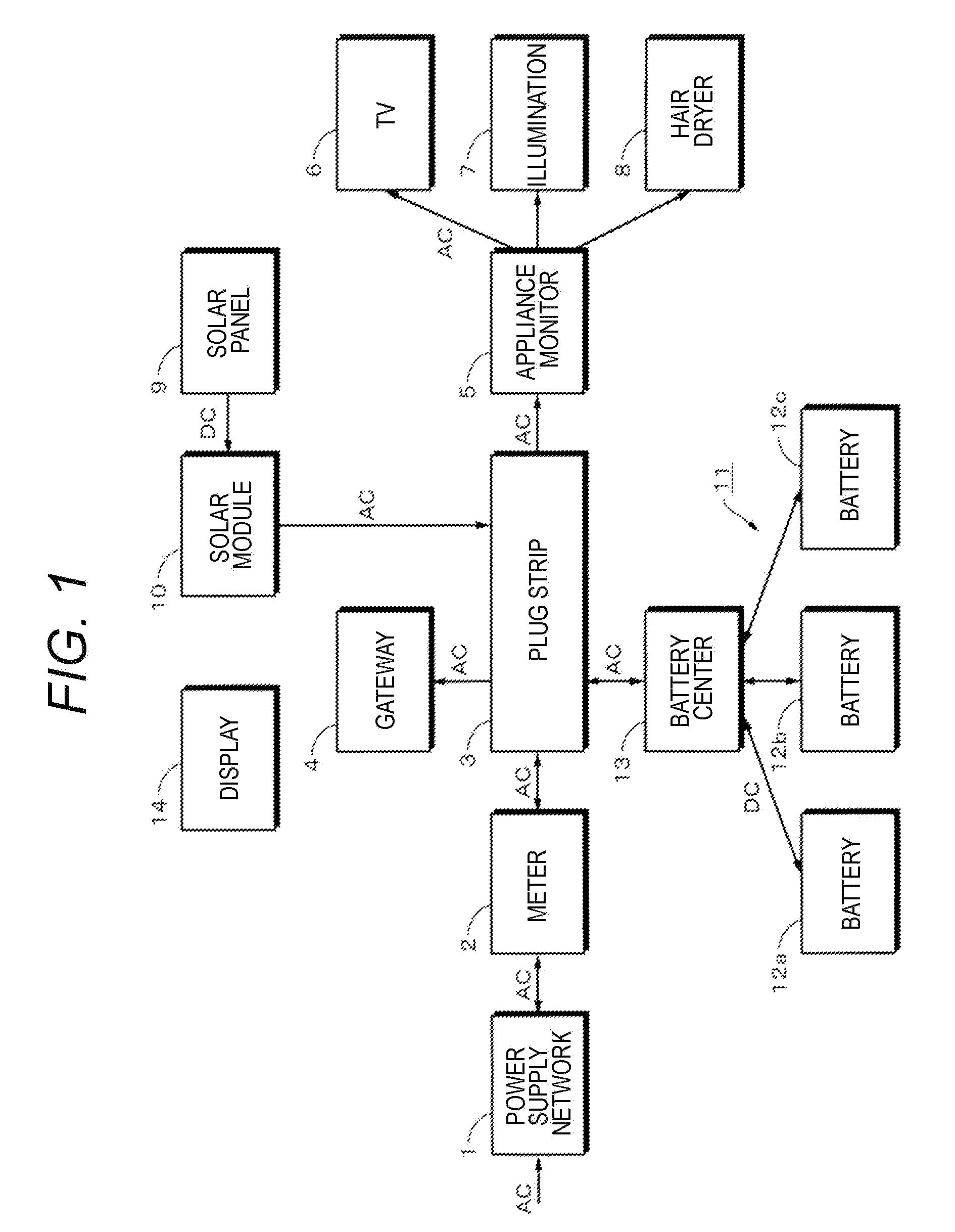
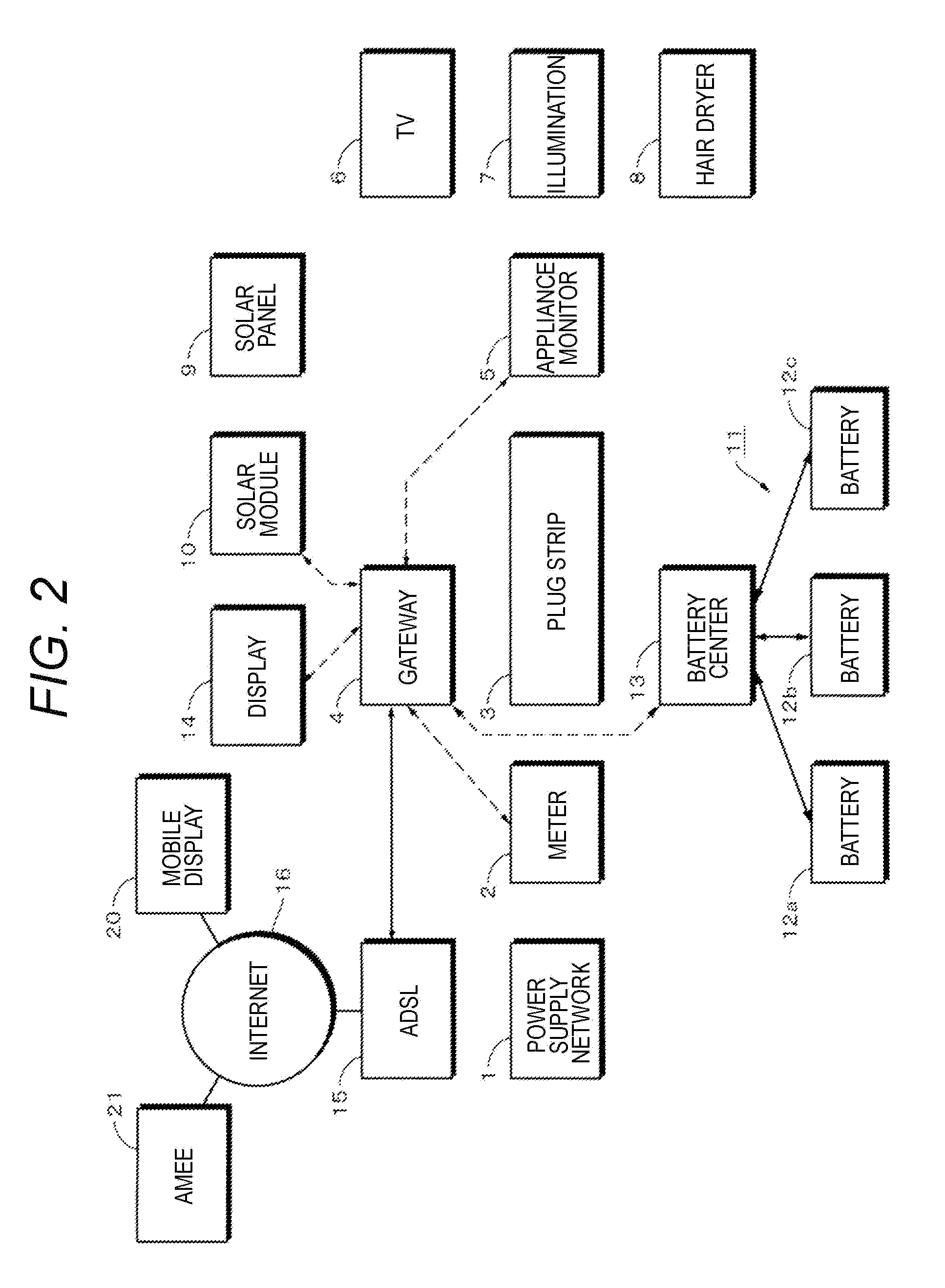
[0026]An example of a power control system for a divided area such as home will be described with reference to FIG. 1. FIG. 1 illustrates power supply paths, and transmission paths for information data, control signals and the like are illustrated in FIG. 2. Furthermore, FIG. 3 is used to illustrate a concept of a home power network. A direct current (DC) and an alternating current (AC) are presented as types of power. For example, an alternating-current power of 220 V (60 Hz) flows in a home power network....


PUM


Abstract

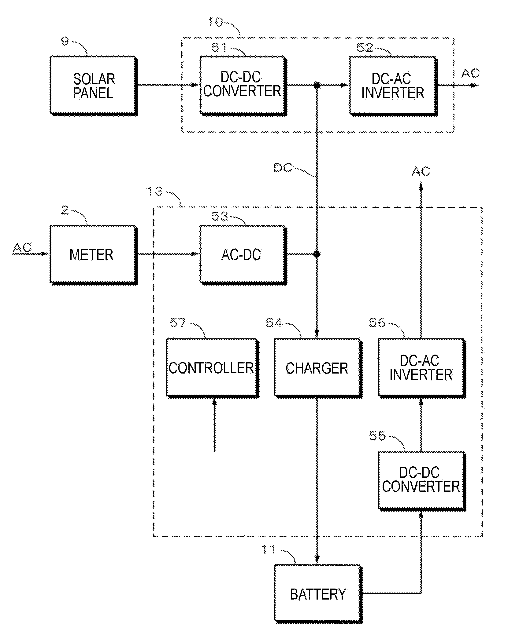
To solve problems arising when a power conditioner equivalent to that connected to a solar panel is connected to a power storage device.Direct-current power generated by the solar panel 9 is supplied to a DC-DC converter 51 and output as a predetermined direct-current voltage. The output voltage of the converter 51 is supplied to a DC-AC inverter 52. Direct-current power generated by the power storage device 11 is supplied to a DC-DC converter 55. Predetermined direct-current power from the converter 55 is supplied to a DC-AC inverter 56. Alternating-current power output by the inverter 56 is supplied to an alternating-current power system at home. The converter 55 is configured to have two output voltages. The first output voltage is a standby voltage. The second voltage is a voltage at which the inverter 56 starts power supply to outside.

Description

TECHNICAL FIELD[0001]The present invention relates to a power control device applied to control of storage and supply by a power accumulating device installed at home, for example.BACKGROUND ART[0002]Recently, there are demands for reducing energy consumption in factories and offices (buildings) and at home. According to statistical data on energy consumption, the ratio of energy consumption by all households to total energy consumption is relatively high, and reduction in energy consumption at home has been an issue. A technique to manage energy consumption at home is called an HEMS (Home Energy Management System). The conventional HEMS is for providing energy saving measures such as on-off control of electrical appliances such as air conditioner and collection of logs of power consumption and the like.[0003]Meanwhile, power generation utilizing renewable energy in place of fossil fuels is becoming into practical use and this trend looks set to be stronger in the future. Examples o...

Claims


Application Information

Patent Timeline
Patent Type & Authority Patents(United States)
IPC IPC(8): H02J1/00H02J3/32H02J3/38H02M1/00
CPCH02J1/00H02J3/32H02J3/383Y02B10/14Y02E10/563Y02E10/566Y02E70/30Y10T307/707H02M7/493H02J2300/24H02J3/381Y02B10/10Y02B70/10Y02E10/56H02M1/0032H02J3/40
Inventor KUBOTA, EIICHIROAVITABILE, ANTONIOMARIELLA, COSTANTINO CRISTIANORUTHERFORD, CHRISTOPHER MICHAELCOLBY, EDWARD GRELLIERBAILEY, NICHOLAS GEORGEKNILL, ALEXANDER CHARLESMEHTA, HARSHUL DEEPAK
Owner SONY CORP
Learn More