Auxiliary device for an agricultural working machine

a technology for agricultural working machines and auxiliary devices, which is applied in the direction of applications, gearing control, harvesters, etc., can solve the problems of increased production costs, increased service life of products, and increased service requirements, so as to increase the operating safety of auxiliary devices, and reliably detect elevated hydraulic fluid temperatures

Active Publication Date: 2016-06-07
CLAAS SAULGAU
View PDF8 Cites 8 Cited by
  • Summary
  • Abstract
  • Description
  • Claims
  • Application Information

AI Technical Summary

Benefits of technology

[0008]The invention thereby discharges heat loss of the hydraulic circuit of the auxiliary device into the hydraulic circuit of the working machine in a manner that is less complex yet reliable.
[0024]Any hydraulic fluid leakage that occurs is captured via leakage lines and is drained into the collecting tank. The collecting tank is preferably equipped with a float switch, which switches the control valve (e.g. a 2 / 2-directional control valve or a shut-off valve). When the collecting tank is full, the unpressurized circulation of the leakage pump (which is preferably designed as a gear pump) is closed, and the leakage pump pumps the contents of the collecting tank via the non-return valve to the discharge connection and from there, preferably into a tank line of the hydraulic system of the working machine. If the collecting tank has been emptied, the leakage pump is switched back into unpressurized circulation by the float switch and the control valve. The non-return valve prevents hydraulic fluid from flowing from the tank, line into the collecting tank. The hydraulic fluid leakage can be selectively and forcibly redirected thereby into the hydraulic circuit of the working machine reliably preventing a backflow of the hydraulic fluid.

Problems solved by technology

Due to the large tank volumes and the hydraulic fluid contents thereof, the production costs are increased and high service costs result over the service life of the product.
A cooler for the hydraulic fluid also requires a cooler drive, which is susceptible to contamination and also results in higher service requirements.

Method used


Image

  • Auxiliary device for an agricultural working machine

Examples


Embodiment Construction

[0031]The following is a detailed description of example embodiments of the invention depicted in the accompanying drawings. The example embodiments are presented in such detail as to clearly communicate the invention and are designed to make such embodiments obvious to a person of ordinary skill in the art. However, the amount of detail offered is not intended to limit the anticipated variations of embodiments; on the contrary, the intention is to cover all modifications, equivalents, and alternatives falling within the spirit and scope of the present invention, as defined by the appended claims.

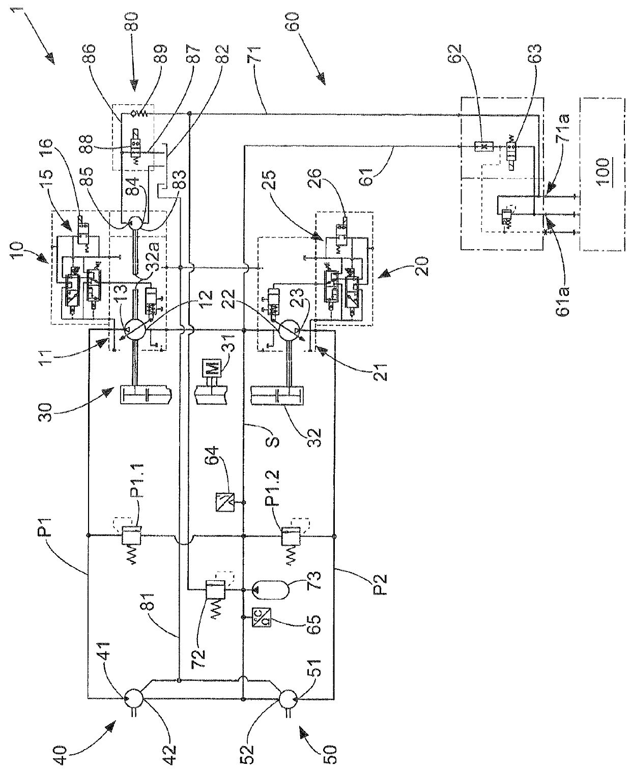
[0032]The non-self-propelled agricultural auxiliary device 1 shown in FIG. 1 is designed as a rotary swather and, is intended to be attached to an agricultural working machine 100, such as a tractor functioning as a towing machine.

[0033]As is evident from FIG. 1, the auxiliary device 1 comprises a hydraulic pump unit 10-20, a drive unit 30 for the hydraulic pump unit 10-20, two hydraulic dr...


PUM


Abstract

An auxiliary device for an agricultural working machine includes a hydraulic pump unit designed to pump a hydraulic fluid at a predetermined working pressure; a drive unit connected to the hydraulic pump unit that drives the hydraulic pump unit at the working pressure; a hydraulic drive having a drive-fluid inlet connected to a pump-fluid outlet of the hydraulic pump unit via a pressure line (P1, P2) and a drive-fluid outlet connected to a pump-fluid inlet via a supply line (S); and a fluid exchange device having a fluid supply line connected to the supply line (S) for a controlled supply of the hydraulic fluid from a hydraulic circuit of the working machine and a fluid discharge line connected to the supply line (S) upstream of the fluid supply line for the controlled discharge of the hydraulic fluid from the supply line (S) into the hydraulic circuit.

Description

CROSS-REFERENCE TO A RELATED APPLICATION[0001]The invention described and claimed hereinbelow is also described in German Priority Document DE 10 2013 001175.2, filed on Jan. 24, 2013. The German Priority Document, the subject matter of which is incorporated herein by reference, provides the basis for a claim of priority of invention under 35 U.S.C. 119(a)-(d).BACKGROUND OF THE INVENTION[0002]The invention relates to an auxiliary device for an agricultural working machine. Such an agricultural auxiliary device can be, for example, a combine-mounted device or a non-self-propelled, drawn agricultural machine such as a self-loading forage wagon or a swather. The self-propelled agricultural working machine is designed, in particular, as a tractor or a similar towing machine, without limitation.[0003]Auxiliary devices for agricultural working machines are known. For example, document DE 695 13 718 T2 makes known a rotary swather as an auxiliary device for an agricultural working machine ...

Claims


Application Information

Patent Timeline
Patent Type & Authority Patents(United States)
IPC IPC(8): F04B49/00F16H61/4165F16H61/4096F16H61/4139A01D69/03F16H61/4078A01D78/10A01B63/10
CPCF04B49/002A01D69/03A01D78/1057F16H61/4078F16H61/4096F16H61/4139F16H61/4165A01B63/10Y10T137/85978
Inventor FEDDE, THOMASZIMMERMANN, MATTHIAS
Owner CLAAS SAULGAU
Why Eureka
Try Eureka