
Method, computer program and rolling mill train for rolling a metal strip

a technology of metal strips and computer programs, applied in the direction of multiple strand roll mill stands, roll mill control devices, manufacturing tools, etc., can solve the problems of uneven strip very quickly, uneven strip, and different elongation of rolling materials, so as to reduce off-gauge length and reduce off-gauge length

Active Publication Date: 2016-06-14
SMS GRP GMBH
View PDF13 Cites 2 Cited by
  • Summary
  • Abstract
  • Description
  • Claims
  • Application Information

AI Technical Summary

Benefits of technology

The present invention is a method of reducing off-gauge lengths in a metal strip during cold rolling. The method involves using the built-up and detected changed tensile stress in the metal strip between two rolling stands to further reduce the initial pass thickness at the first active rolling stand. This allows for a more effective reduction ofunwanted off-gauge lengths and ensures better quality metal strips. The method also allows for the optimalization of the initial pass thickness of individual rolling stands in a rolling mill train to reduce off-gauge lengths even further.

Problems solved by technology

There are two essential reasons for carrying out this method: On the one hand, the force and work demand during rolling without tension is considerably higher than with tension and, on the other hand, especially in the case of the small thicknesses used in cold rolling, the strip very rapidly becomes uneven, if the roll gap profile does not fit the incoming profile of the metal strip, and the rolling material thus undergoes different elongations over the strip width.
The disadvantage of this method is that, at the strip head, a considerable length of the metal strip does not have the desired thickness, and therefore has to be scrapped as off-gauge length.
In the conventional mode of operation, the roll gap of the individual rolling stands is also opened here, and this also results in off-gauge lengths.

Method used


Image

  • Method, computer program and rolling mill train for rolling a metal strip
  • Method, computer program and rolling mill train for rolling a metal strip
  • Method, computer program and rolling mill train for rolling a metal strip

Examples


Embodiment Construction

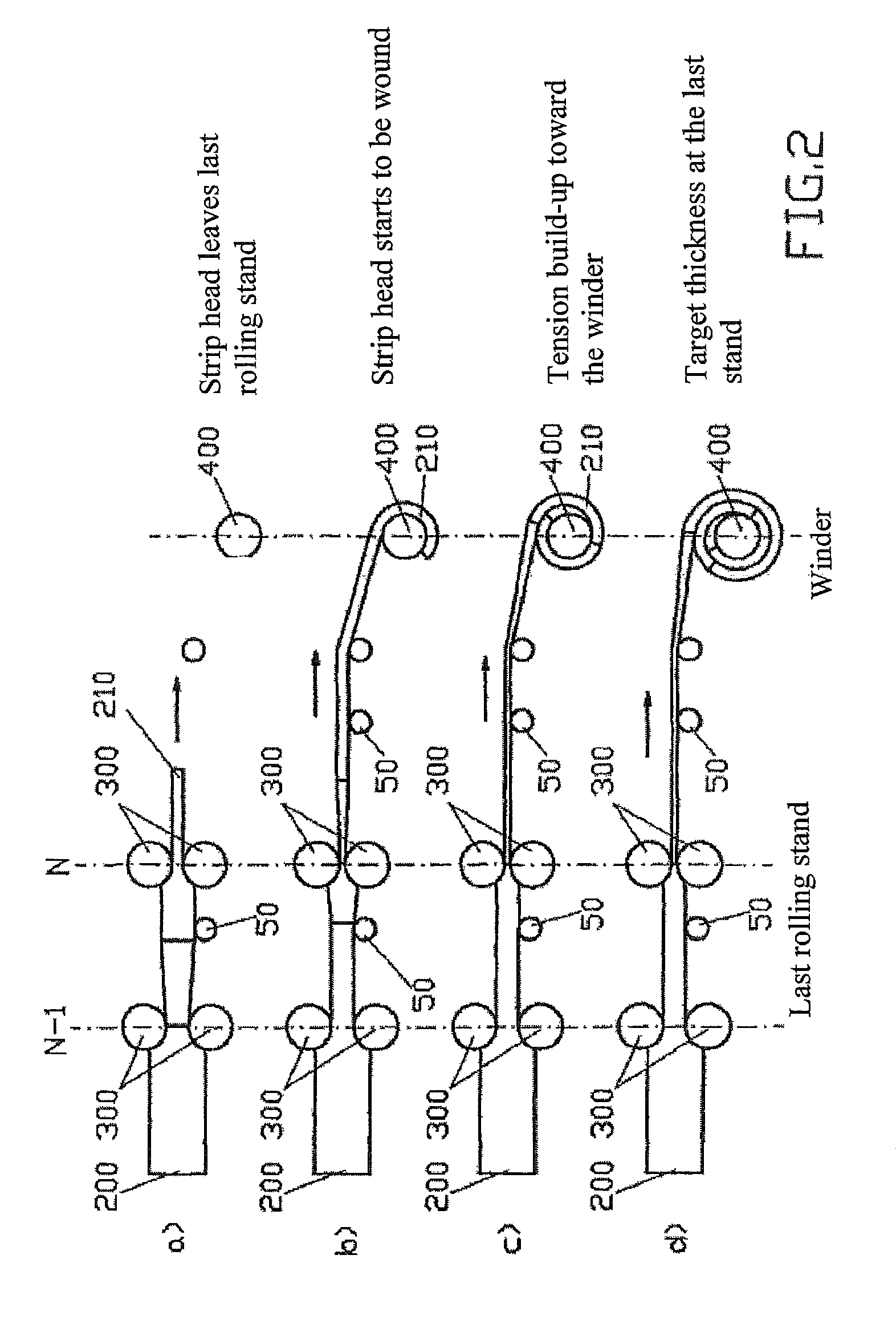
[0046]The invention is described in further detail below in reference to FIGS. 1 and 2. In FIGS. 1 and 2, identical technical elements are denoted with identical reference numerals. Two circles or rollers arranged one above the other in pairs always denote a working roller pair with opened roll gap in FIGS. 1 and 2.

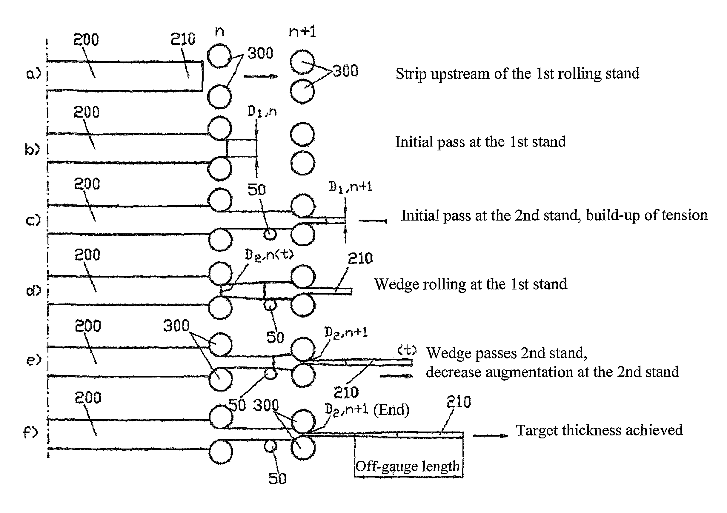
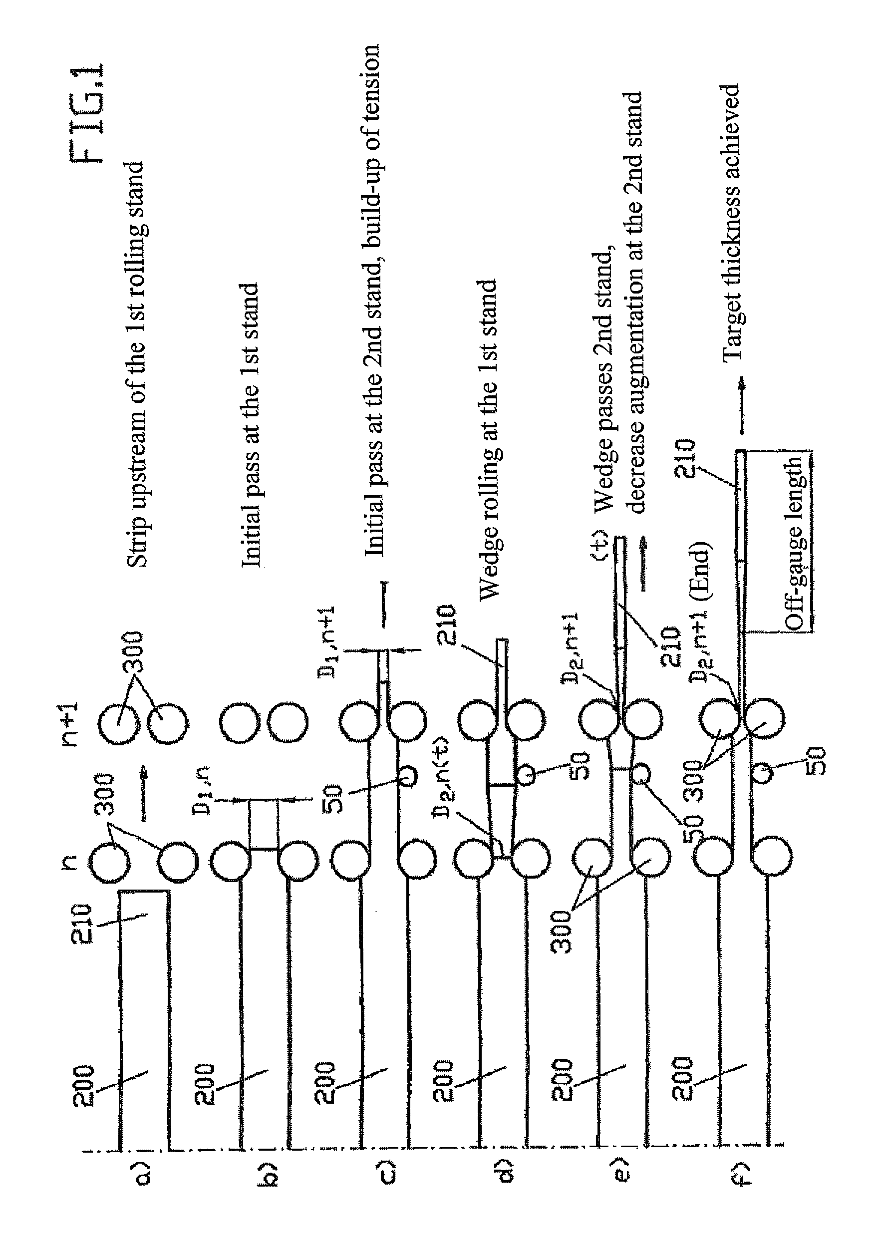
[0047]According to FIG. 1, the method according to the invention, in a first process step a), provides for setting the roll gap of the n-th rolling stand to a predetermined first initial pass thickness D1,n, before the metal strip 200 passes with the strip head 210 through the roll gap of the n-th rolling stand; see FIG. 1a). The metal strip 200 is then moved on with its strip head 210 to the n-th rolling stand, where it, including its strip head 210, undergoes a reduction of its thickness to the first initial pass thickness D1n, see FIG. 1b). The metal strip 200 is then transported further according to FIG. 1c) from the n-th rolling stand to the n+1-th rolling stand, whe...


PUM

PropertyMeasurementUnit
Thicknessaaaaaaaaaa
Tensile stressaaaaaaaaaa

Abstract

The invention relates to a method, a computer program and a rolling mill train for cold rolling a metal strip (200). In order to achieve a shortening of undesired off-gauge lengths, the method according to the invention provides that the head (210) of the metal strip (200) already undergoes a thickness reduction at the first active rolling stand (n) in the rolling mill train, and then is transported on to the next rolling stand, in order to undergo a further thickness reduction there. The method according to the invention also provides for further reducing the initial pass thickness at the n-th rolling stand in accordance with the tensile stress that has built up in the meantime between the n+1-th and the n-th rolling stand.

Description

CROSS REFERENCE TO RELATED APPLICATIONS[0001]This application is a national phase of PCT application No. PCT / EP2012 / 060698, filed Jun. 6, 2012, which claims priority to DE patent application No. 102011106327.0, filed Jun. 8, 2011, and DE patent application No. 102011078150.1, filed Jun. 27, 2011, all of which are incorporated herein by reference.BACKGROUND OF THE INVENTION[0002]1. Field of the Invention[0003]The invention relates to a method, a computer program and a rolling mill train for rolling a metal strip. The rolling mill train comprises N active rolling stands arranged one after the other in the rolling direction.[0004]2. Description of the Prior Art[0005]In principle, such methods, computer programs and rolling stands are known in the prior art. Thus, from the International Publication WO 2009 / 049964 A1, a rolling mill train having at least two rolling stands is known, wherein the metal strip as it passes the rolling stand undergoes in each case a thickness reduction, since...

Claims


Application Information

Patent Timeline
IPC IPC(8): B21B13/00B21B37/16B21B37/48B21B37/58
CPCB21B37/58B21B13/00B21B37/16B21B37/48B21B2271/02B21B2273/08B21B2013/006
Inventor RITTER, ANDREASSUDAU, PETERKOCH, MARKUS
Owner SMS GRP GMBH
Learn More