Light source with laser pumping and method for generating radiation

a laser pumping and light source technology, applied in the direction of electric discharge tubes, electric discharge lamps, electrical equipment, etc., can solve the problems of not providing measures to suppress laser radiation in plasma radiation beams, not optimal for obtaining radiation of the highest brightness, and limiting the scope of applications of this light source, so as to improve the protection of optical systems and increase the brightness of broadband plasma radiation

Active Publication Date: 2016-06-14
OBSHCHESTVO S OGRANICHENNOJ OTVETSTVENNOSTJU RND ISAN
View PDF6 Cites 5 Cited by
  • Summary
  • Abstract
  • Description
  • Claims
  • Application Information

AI Technical Summary

Benefits of technology

[0013]The object of the invention is optimization of the laser pumping mode, form of the region of radiating plasma, geometry of the optical system for collecting plasma radiation to increase brightness of broadband plasma radiation, as well as improved protection of the optical system for collecting plasma radiation from laser radiation.
[0014]The technical result of the invention is the expansion of functional possibilities of the laser-pumped light source due to increased brightness, increase the absorption coefficient of laser irradiation by plasma, significant decrease the numerical aperture of the blocked divergent laser beam passing through the plasma.
[0029]Another invention from this group of inventions relates to a method of generating radiation, wherein the plasma is ignited in a chamber with gas and from a first side of the chamber a laser beam, in continuous mode, is focused into the chamber, a region of radiating plasma is formed along an axis of focused laser beam, with a small, ranging from 0.1 to 0.5, aspect ratio d / l of its dimensions, wherein brightness of plasma radiation in a direction along the axis of the focused laser beam is close to a maximum attainable for a specified laser power, with properties of plasma lens, providing a decrease in a numerical aperture NA2 of a divergent laser beam from a second side of the chamber compared to a numerical aperture NA1 of the focused laser beam from the first side of the chamber: NA2<NA1; an output plasma radiation onto an optical system, located on the second side of the chamber, for collecting plasma radiation is carried out using a divergent beam of plasma radiation, with a direction of an optical axis primarily coinciding with the direction of the axis of the focused laser beam, and by using the blocker prevent the passage of the divergent laser beam to the optical system for collecting plasma radiation.

Problems solved by technology

However, collection of radiation is carried out primarily in the direction close to normal, relative to the axis of the focused laser beam, which may not be optimal for obtaining radiation of the highest brightness.
In addition, within the plasma radiation beam there is a laser radiation present that is not completely absorbed by plasma, which limits the scope of applications of this light source.
However, in the solution US20070228300 does not provide measures to suppress laser radiation in the plasma radiation beam.
However, the blocker, preferably mounted on one of the electrodes for starting plasma ignition, is placed directly in the light source chamber and exposed to large radiating loads.
This complicates the design of the chamber and light source as a whole.
In addition, the blocker does not allow output of light along the axis of the focused laser beams.
As a result, the plasma radiation are directed at the mirror of the optical collector at large angles to the axis of the focused laser beam, which is not optimal for obtaining high-brightness radiation.
However, the geometry of the light source, its optical collector, and region of radiating plasma, are not optimal for achieving maximum radiation brightness.

Method used


Image

  • Light source with laser pumping and method for generating radiation
  • Light source with laser pumping and method for generating radiation
  • Light source with laser pumping and method for generating radiation

Examples


Embodiment Construction

[0038]This description is intended to illustrate the invention embodiments and not the entire scope of the present invention.

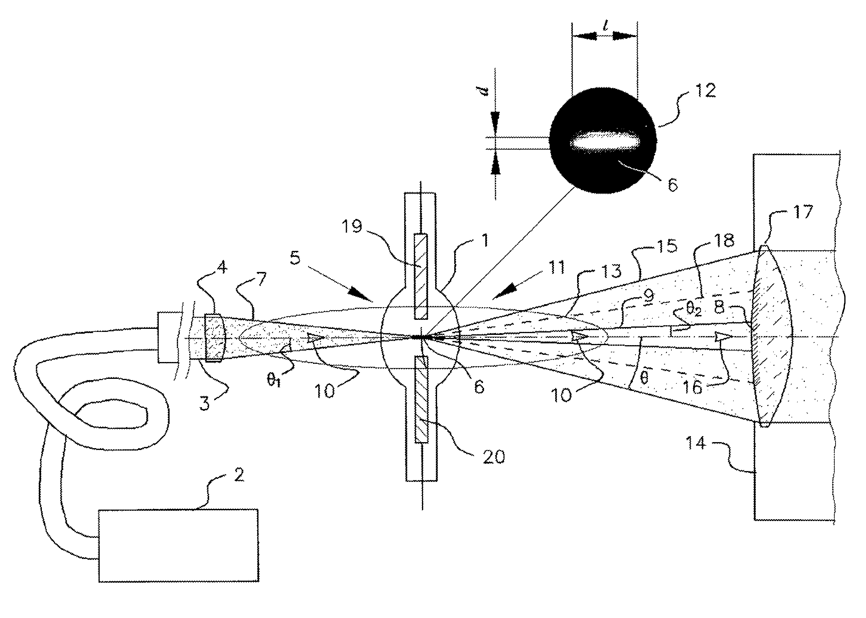
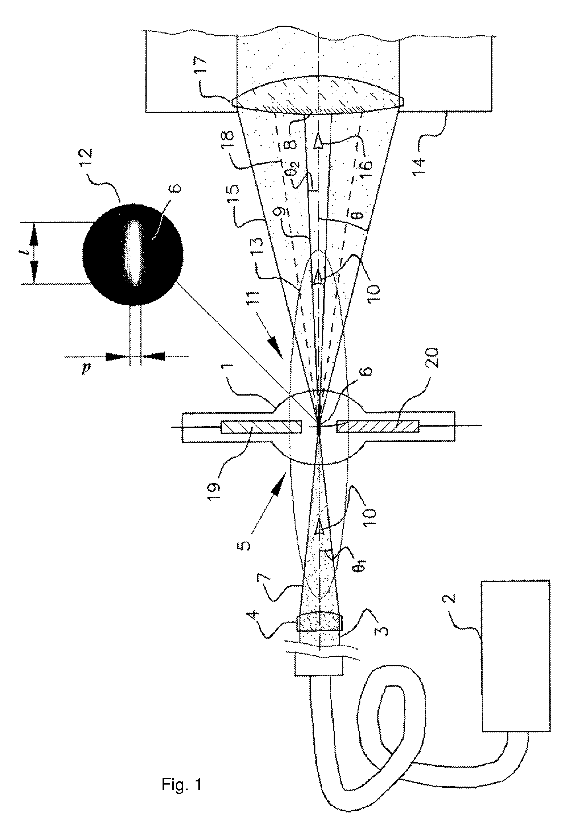
[0039]In accordance with an example of the invention embodiment, laser-pumped light source includes a chamber 1, containing gas, in particular, high pressure xenon at 10-20 atmospheres; laser 2, providing the laser beam 3; optical element 4, focusing the laser beam from the first side 5 of the chamber 1, region of radiating plasma 6, created in chamber 1 by the focused laser beam 7; blocker 8, mounted on the axis 10 of the divergent laser beam 9 from the second side 11 of chamber 1, opposite the first side 5, (FIG. 1).

[0040]Wherein the numerical aperture NA1===sin θ1 for the focused laser beam 7 and power of the laser 2, are chosen such that[0041]region of radiating plasma 6 is extended along the axis 10 of the focused laser beam 7, having a small, in the range of 0.1 to 0.5, aspect ratio d / l transverse d and longitudinal l dimensions of the region of radiatin...


PUM


Abstract

The invention relates to light sources with laser pumping and to methods for generating radiation with a high luminance in the ultraviolet (UV) and visible spectral ranges. The technical result of the invention includes extending the functional possibilities of a light source with laser pumping by virtue of increasing the luminance, increasing the coefficient of absorption of the laser radiation by a plasma, and significantly reducing the numerical aperture of a divergent laser beam which is to be occluded and which is passing through the plasma. The device comprises a chamber containing a gas, a laser producing a laser beam, an optical element, a region of radiating plasma produced in the chamber by the focused laser beam, an occluder, which is mounted on the axis of the divergent laser beam on the second side of the chamber, and an optical system for collecting plasma radiation.

Description

CROSS-REFERENCE TO RELATED APPLICATIONS[0001]This application is a national stage application of PCT / RU2013 / 000740 filed on Aug. 23, 2013 which claims priority to Russian application RU2012154354 filed on Dec. 17, 2012 currently issued as a patent RU2539970.FIELD OF THE INVENTION[0002]The invention relates to laser-pumped light sources and methods for generating a high brightness radiation in ultraviolet (UV) and visible spectral ranges.PRIOR ART[0003]The plasma of various gases, created by focused beam of a continuous-wave laser at gas pressures of 10-20 atm., is one of the highest-brightness sources of continuous radiation in the wide spectral range of 170-880 nm. As a high-efficient plasma fuel, xenon (Xe), mercury vapors, including mixtures with inert gases, as well as vapors of other metals, and various gas mixtures, including halogenous ones, may be used. Compared to arc lamps, these sources have large lifetimes. The high spectral brightness of laser-pumped light sources, arou...

Claims


Application Information

Patent Timeline
Patent Type & Authority Patents(United States)
IPC IPC(8): H01J11/00H01J63/08H01J61/02
CPCH01J63/08H01J61/025H01J65/04H01J61/76H01J61/54
Inventor ANTSIFEROV, PAVEL STANISLAVOVICHKOSHELEV, KONSTANTIN NIKOLAEVICHKRIVTSUN, VLADIMIR MIKHAILOVICHLASH, ALEKSANDR ANDREEVICH
Owner OBSHCHESTVO S OGRANICHENNOJ OTVETSTVENNOSTJU RND ISAN
Why Eureka
Try Eureka