

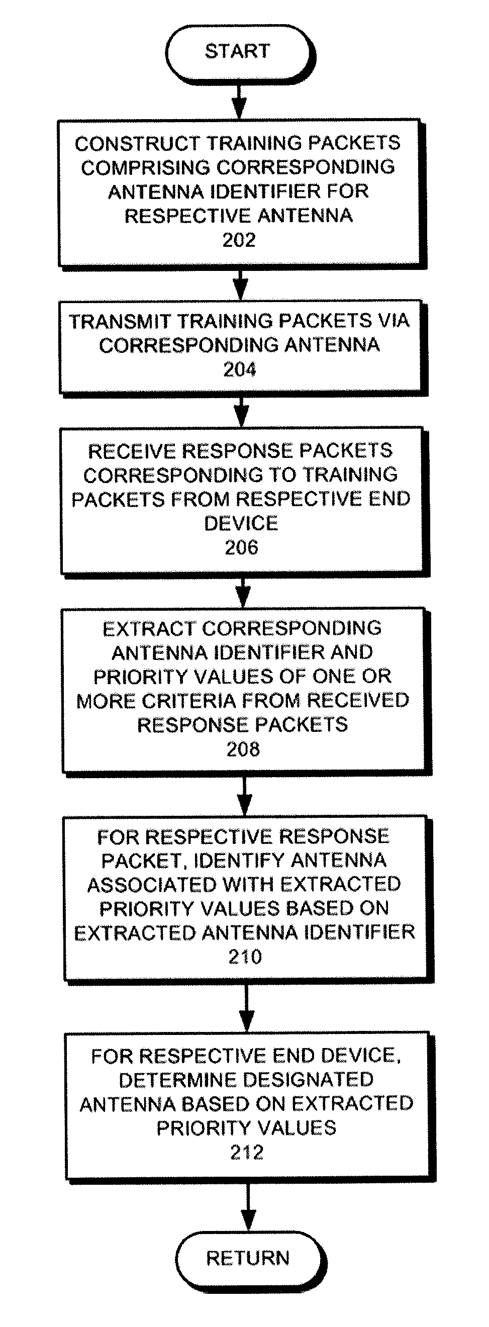
Methods of operating an access point using a plurality of directional beams
a technology of access points and beams, applied in diversity/multi-antenna systems, particular array feeding systems, wireless communication, etc., can solve the problems of low utilization of wireless bandwidth provided by antennas, interference of directional antennas, and large lenses
- Summary
- Abstract
- Description
- Claims
- Application Information
AI Technical Summary
Benefits of technology
Problems solved by technology
Method used
Image

Examples
Embodiment Construction
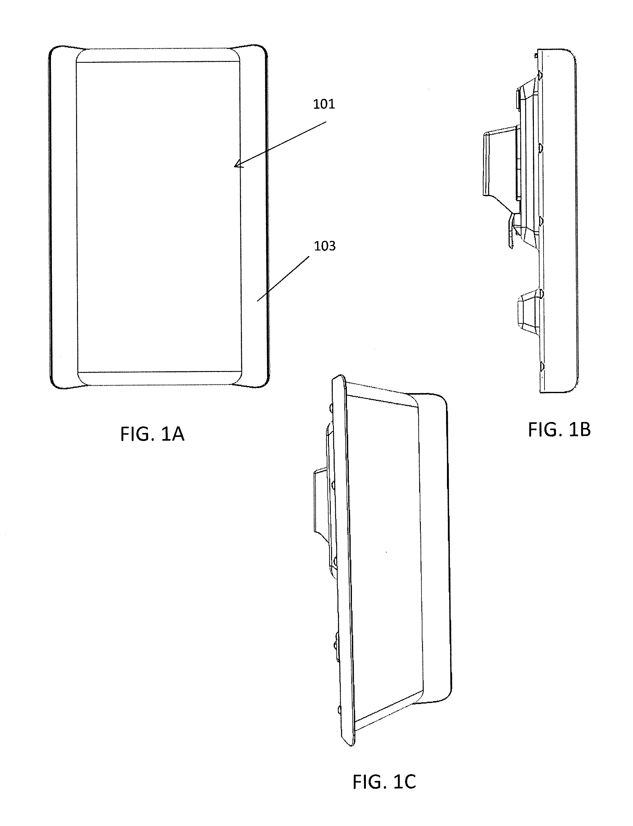
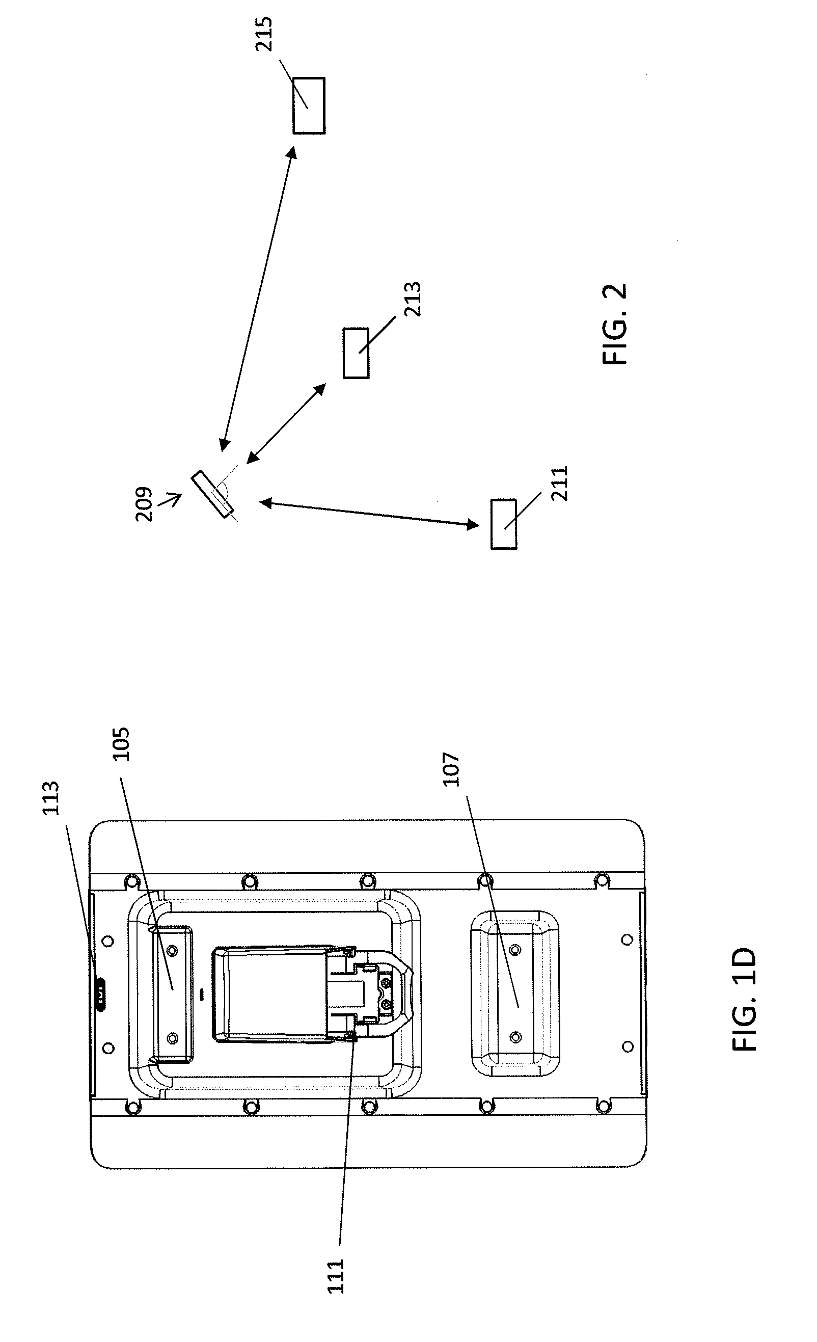
[0121]Phased array antennas are described herein, including phased array antennas that include a compact, electronic lens for steering (beamforming) the antenna. Features of the array antennas, and of systems including such antennas, are described in greater detail below, and may include: compact, electronic lenses (e.g., lacunated lenses) for steering a phased array antenna, phased array antennas incorporating such compact electronic lenses, phased array antennas adapted for use with a removable, self-contained RF radio (transceiver) device, methods and devices for identifying the type of antenna (including the type of phased array antenna) to which a removable, self-contained RF radio is connected, methods and device for controlling a phased array antenna by a removable, self-contained RF radio, and arrangements of antenna (emitting) elements within a phased array antenna. Also described herein are systems and methods of operating an access point using an antenna array, which may ...
PUM
 Abstract
Description
Claims
Application Information