Moisture sensor and/or defogger with Bayesian improvements, and related methods

a technology of moisture sensor and defogger, which is applied in the field of moisture sensor and/or defogger, can solve the problems of false reading/wipe, hazardous driving conditions for drivers, passengers, pedestrians, etc., and achieve the effect of reducing driving hazards and reducing driver distractions

Active Publication Date: 2016-06-21
GUARDIAN GLASS LLC
View PDF68 Cites 11 Cited by
  • Summary
  • Abstract
  • Description
  • Claims
  • Application Information

AI Technical Summary

Benefits of technology

[0003]The presence of moisture (e.g., rain or condensation) and / or other material or debris on vehicle windshields and / or backlites may create hazardous driving conditions for drivers, passengers, and pedestrians if not promptly removed. Wiper blades are a well-known, common way to remove such materials and reduce the hazards of driving during dangerous conditions. Rain sensors have been developed to detect the presence of moisture (e.g., rain or other condensation) on a vehicle windshield, and to turn on and off wipers, as necessary, when such moisture is detected. Automatically detecting rain, sleet, fog, and the like, and taking appropriate action—for example, turning on / off wiper blades at a proper speed—potentially reduces distractions to the driver, allowing the driver to better concentrate on the road ahead. However, inappropriately turning on / off wipers or failing to actuate wipers when moisture is present may also create hazardous conditions. Moreover, such systems are also susceptible to “dirt” distractions which may cause false reads / wipes when dirt is on the windshield.
[0015]In certain example embodiments of this invention, there is provided a rain sensor comprising: at least one sensing capacitor that is sensitive to moisture on an external surface of a window, the sensing capacitor including a first capacitor electrode that receives a charging signal and a second capacitor electrode spaced apart from the first capacitor electrode; and wherein the second capacitor electrode is floating so that the sensing capacitor is isolated from ground. The floating characteristic has been found to be advantageous in that it permits false reads due to EMI or external objects (e.g., human hand) to be reduced or prevented.
[0025]In certain example embodiments of this invention, capacitors are formed based on a fractal pattern. For example and without limitation, one or more of the capacitors may be formed based on a fractal pattern, such as a Hilbert fractal pattern. Other capacitive fractal patterns may also be used, including but not limited to a Cantor set. These fractal structures maximize or enlarge the periphery and thus result in a large capacitance for a given area. The use of two dimensional fractal designs also allows the sensor to occupy a small amount of physical space on the window while at the same time being electrically larger than its physical size. The concentration of lateral flux in a fractal geometry may also allow the sensor to detect rain / water not necessarily spread over the actual physical area of the sensor in certain example embodiments of this invention. Furthermore, in its higher iteration(s) a fractal capacitor(s) has an attribute of being its own Faraday shield or quasi-Faraday shield. Also, in certain example embodiments, the rain sensor may be electrically connected to a Local Interconnect Bus of the vehicle.

Problems solved by technology

The presence of moisture (e.g., rain or condensation) and / or other material or debris on vehicle windshields and / or backlites may create hazardous driving conditions for drivers, passengers, and pedestrians if not promptly removed.
However, inappropriately turning on / off wipers or failing to actuate wipers when moisture is present may also create hazardous conditions.
Moreover, such systems are also susceptible to “dirt” distractions which may cause false reads / wipes when dirt is on the windshield.
However, these optical techniques have limited sensing areas, are fairly expensive, and may result in erroneous detection indications due to the use of optical imaging as the sole detection method.
These fractal structures maximize or enlarge the periphery and thus result in a large capacitance for a given area.

Method used


Image

  • Moisture sensor and/or defogger with Bayesian improvements, and related methods
  • Moisture sensor and/or defogger with Bayesian improvements, and related methods
  • Moisture sensor and/or defogger with Bayesian improvements, and related methods

Examples


Embodiment Construction

[0119]Referring now more particularly to the accompanying drawings in which like reference numerals indicate like parts throughout the several views.

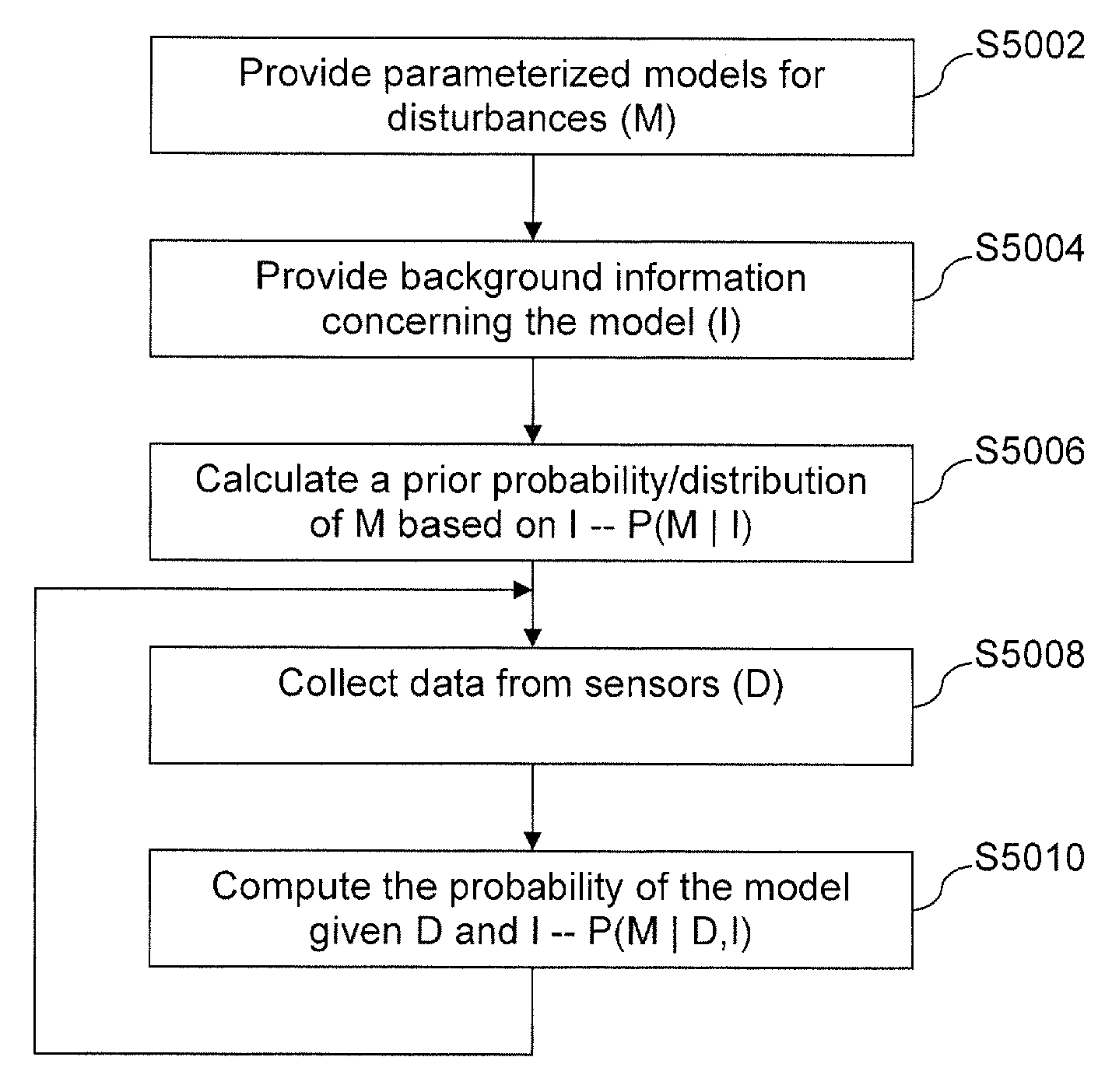
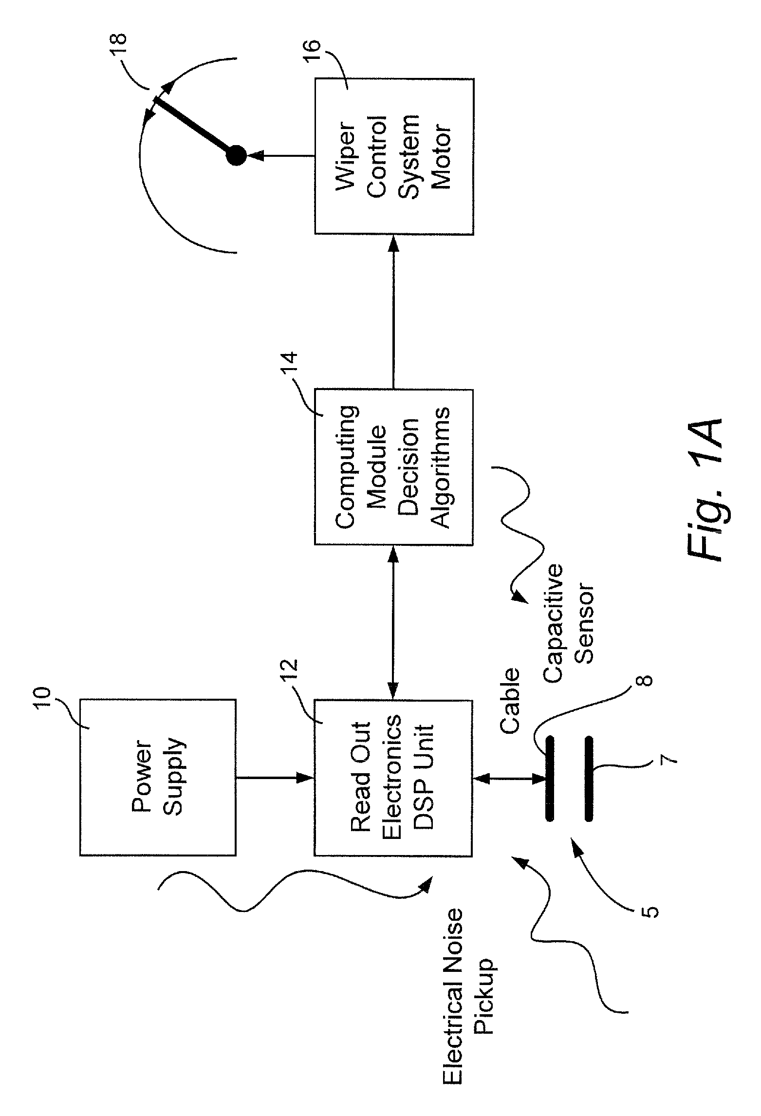
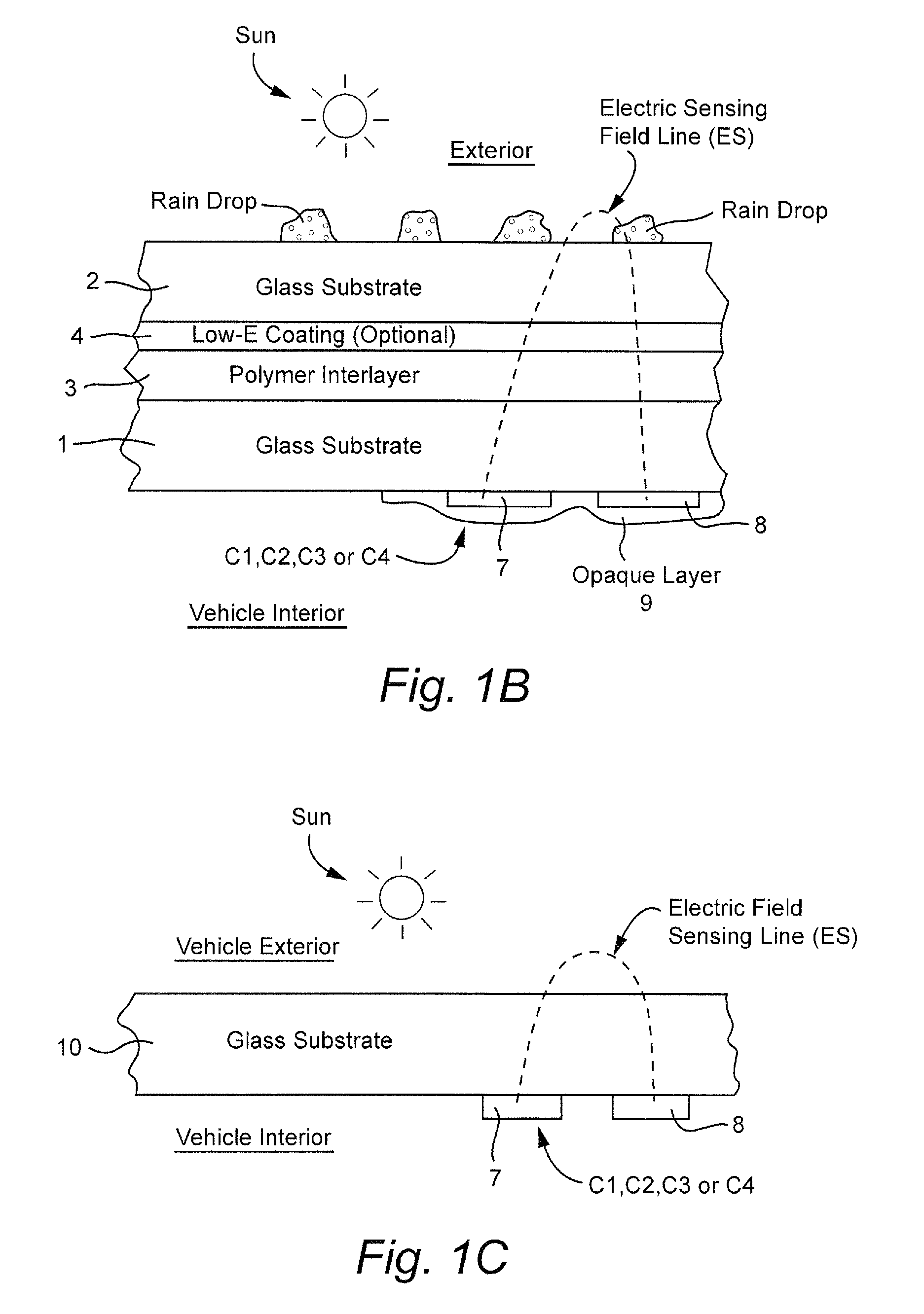
[0120]In certain example embodiments of this invention, a moisture (e.g., rain) sensor system and / or method is provided and includes capacitance-based detection which translates a physical input signal (e.g., the presence of a drop of water on a windshield, or the like) into a digital electrical voltage signal which is received and interpreted by a software program(s) or circuit(s) that decides whether windshield wipers should be activated, and, if so, optionally their proper speed. Thus, capacitive coupling is used to detect water and / or other material in the exterior surface of a window such as a vehicle windshield, sunroof, and / or backlite. It will be appreciated that computational methods may be performed by hardware or a combination of hardware and software in different example embodiments of this invention. In certain example embo...


PUM

PropertyMeasurementUnit
meandering lengthaaaaaaaaaa

Abstract

In certain example embodiments, moisture sensors, defoggers, etc., and / or related methods, are provided. More particularly, certain example embodiments relate to moisture sensors and / or defoggers that may be used in various applications such as, for example, refrigerator / freezer merchandisers, vehicle windows, building windows, etc. When condensation or moisture is detected, an appropriate action may be taken (e.g., actuating windshield wipers, turning on a defroster, triggering the heating of a merchandiser door or window, etc.). Bayesian approaches optionally may be implemented in certain example embodiments in an attempt to improve moisture detection accuracy. For instance, models of various types of disturbances may be developed and, based on live data and a priori information known about the model, a probability of the model being accurate is calculated. If a threshold value is met, the model may be considered a match and, optionally, a corresponding appropriate action may be taken.

Description

CROSS-REFERENCES TO RELATED APPLICATIONS[0001]This application is a continuation-in-part (CIP) of U.S. Ser. No. 12 / 076,238, filed Mar. 14, 2008 now U.S. Pat. No. 8,634,988, which is a CIP of U.S. Ser. No. 11 / 700,251, filed Jan. 31, 2007 now U.S. Pat. No. 7,551,095, which is a CIP of each of U.S. Ser. Nos. 11 / 340,847, filed Jan. 27, 2006 now U.S. Pat. No. 7,561,094, Ser. No. 11 / 340,864, filed Jan. 27, 2006 now U.S. Pat. No. 7,492,270, Ser. No. 11 / 340,859, filed Jan. 27, 2006 now U.S. Pat. No. 7,561,055, and Ser. No. 11 / 340,869, filed Jan. 27, 2006 now U.S. Pat. No. 7,516,002, all of which claim priority on U.S. Provisional Patent Application No. 60 / 757,479, filed Jan. 10, 2006, the disclosures of which are all hereby incorporated herein by reference.FIELD OF THE INVENTION[0002]Certain example embodiments relate to moisture sensors and / or defoggers, and / or related methods. More particularly, certain example embodiments relate to moisture sensors and / or defoggers that may be used in va...

Claims


Application Information

Patent Timeline
Patent Type & Authority Patents(United States)
IPC IPC(8): B60S1/08B60Q1/14B60S1/02B32B17/10G01D5/24
CPCB32B17/10036B32B17/10174B32B17/10761B60S1/0825B60S1/087B60Q1/1423G01D5/24B60S1/0818B60S1/0822B60Q2300/112B60Q2300/314G06N7/01G01J1/42G01N27/223
Inventor VEERASAMY, VIJAYEN S.
Owner GUARDIAN GLASS LLC
Why Eureka
Try Eureka