Air flow regulator

a technology of air flow regulator and air flow, which is applied in the field of plastic article manufacture, can solve the problems of high cost, large rush of air under atmospheric pressure, and substantial movement of materials, and achieve the effect of facilitating the expansion of the pneumatic plastic resin pellet conveying system and reducing the cost of those systems

Inactive Publication Date: 2016-06-21
MAGUIRE STEPHEN B
View PDF75 Cites 14 Cited by
  • Summary
  • Abstract
  • Description
  • Claims
  • Application Information

AI Technical Summary

Benefits of technology

[0019]The instant invention provides an improvement to known pneumatic plastic resin pellet conveying systems, reducing the costs of those systems while providing more consistent control of air speed and delivered cubic feet per minute of air for individual receivers. The invention also facilitates easy expansion of the pneumatic plastic resin pellet conveying system as the system grows. Such expandable systems are made feasible by the inventive vacuum or air flow controller embodying aspects of this invention. The vacuum or air flow controller is a new cubic feet per minute air flow regulator.
[0020]By adding a flow regulator manifesting aspects of this invention to every receiver, plant operators can limit air flow in cubic feet per minute to a value that is ideal for that particular receiver, considering conduit diameter and distance over which the plastic resin pellets must be conveyed through that conduit.
[0021]Use of the air flow regulator in accordance with this invention allows pneumatic plastic resin pellet conveying systems to utilize a single large high horsepower vacuum pump. In accordance with the invention, each receiver in a facility is fitted with a vacuum flow regulator embodying the invention so the flow for each receiver in cubic feet per minute flow is self-limiting. The invention eliminates the need to size vacuum pumps or blowers to a specific material conduit size or conveyance distance. The flow regulator of the invention permits operators to run a very large vacuum pump or blower at a speed that will maintain a desired high level of vacuum throughout the entire vacuum or pneumatic plastic resin pellet conveying system.

Problems solved by technology

With such an approach, the positive pressure results in a movement of substantial amounts of air which may be used to carry plastic resin pellets.
Use of such high capacity vacuum pumps results in a big rush of below atmospheric pressure air through the line, carrying the plastic resin pellets over a long distance.
Of course, the higher the number of receivers served by the system, the higher the cost.
If air flow is too slow, the plastic resin pellets fall out of the air stream, lie on the bottom of the conduit, and there is risk of clogging the conduit.
If air flow is too fast, the plastic resin pellets can skid along the conduit surface.
In such case, harder, more brittle plastic resin pellets are damaged, resulting in dust within the conduit, which when drawn into the vacuum pump can damage the vacuum pump and render the system inoperative.
This results in “angel hair”—long, wispy-thin strands of plastic film which eventually clog the conduit and cause the system to shut down.
However, a single 20 horsepower blower would result in far too high a conveying speed for the plastic resin pellets through any reasonable size conduit.
Even with careful planning and design, results achieved by such pneumatic plastic resin pellet conveying systems are not consistent.

Method used


Image

  • Air flow regulator
  • Air flow regulator
  • Air flow regulator

Examples


Embodiment Construction

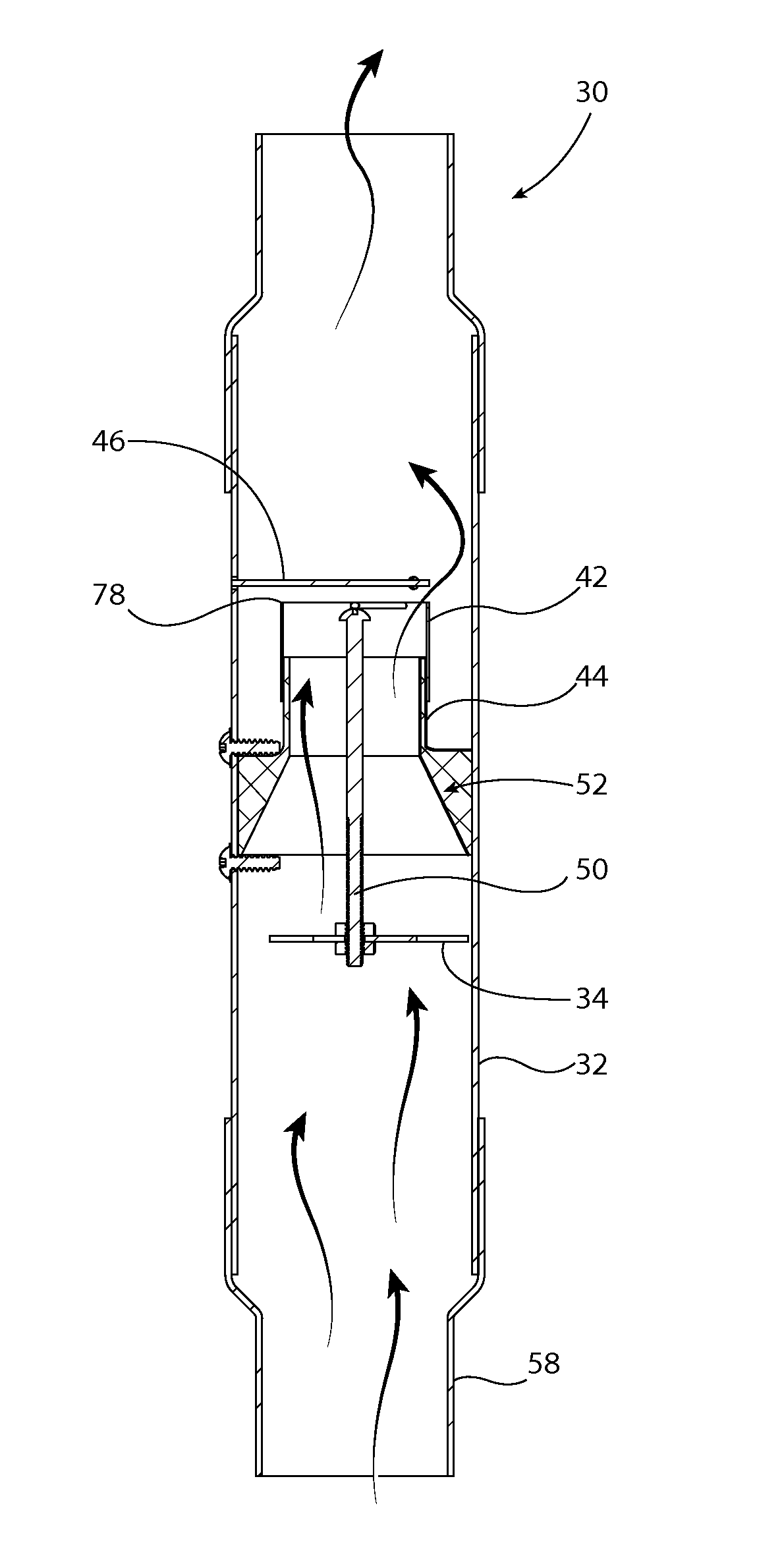
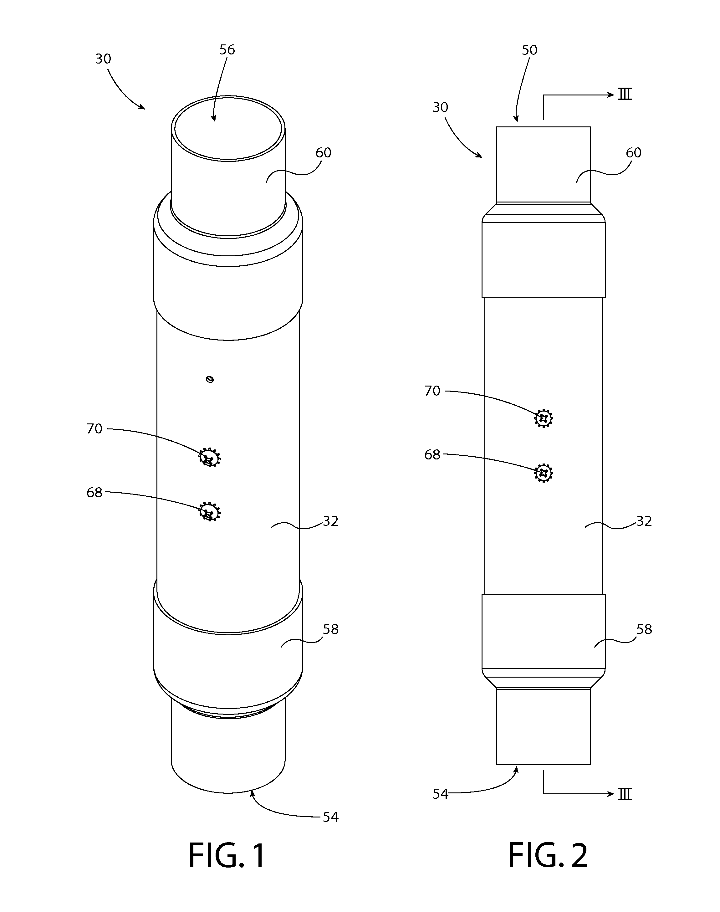
[0052]Referring to the drawings in general and to FIG. 1 in particular, air flow limiter 30 is preferably in the general form of a vertically oriented tube, preferably having inlet and outlet ends 54, 56 respectively. The tubular character of air flow limiter 30 is apparent from FIGS. 1 through 6, where air flow limiter 30 preferably includes a vertically oriented exterior tube 32, with open-end caps 58, 60 defining and providing open inlet and outlet ends 54, 56 respectively. End caps 58, 60 are open, of generally cylindrical configuration, and are configured to fit closely about vertically oriented tube 32 so as to provide a substantially air tight fit between end caps 54, 56 and tube 32.

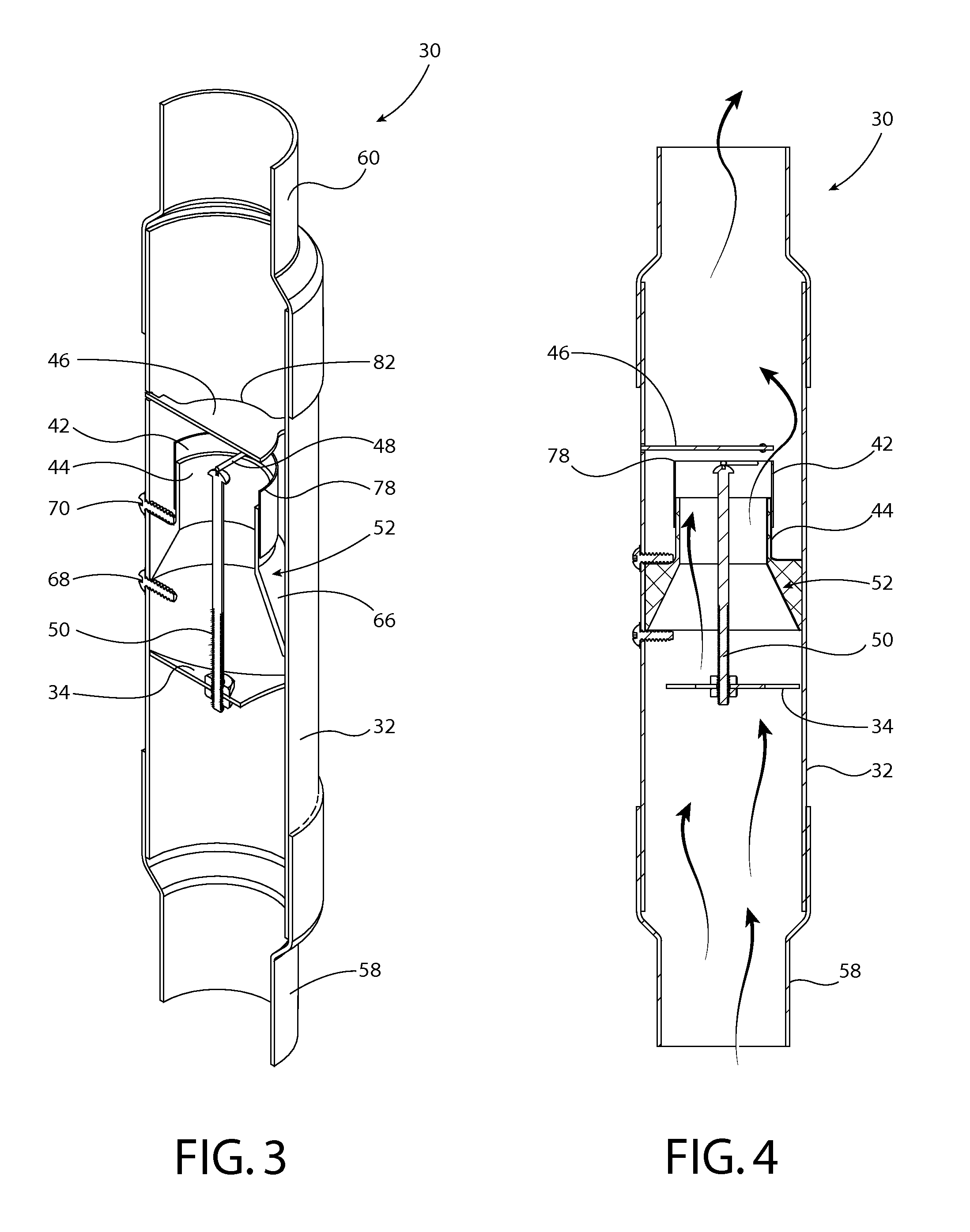
[0053]As illustrated in FIG. 3, air flow limiter 30 preferably includes, within vertically oriented exterior tube 32, a horizontally positioned plate 46, which is oriented perpendicularly to the axis of tube 32. Plate 46 is preferably configured as a circular disk of lesser diameter than the inner...


PUM


Abstract

Method and apparatus for air flow regulation comprise a vertically oriented tube and a sail assembly positioned in the tube and moveable therewithin responsively to air flow through the tube to regulate rate of air flow through the tube and stop air flow through the tube upon air flow rate through the tube exceeding a preselected value.

Description

BACKGROUND OF THE INVENTION[0001]This invention relates to manufacture of plastic articles and more particularly relates to pneumatic conveyance and processing of plastic resin pellets prior to molding or extrusion of those pellets into a finished or semi-finished plastic product.DESCRIPTION OF THE PRIOR ART[0002]In facilities that fabricate plastic products by molding or extrusion, it is common to use “vacuum systems” to pneumatically convey pellets of thermoplastic resin, prior to molding or extrusion of those pellets into a finished or semi-finished product, from a central storage point to each of the many compression or injection plastic molding machines or plastic extruders scattered throughout the facility. Individual loaders, which are referred to as “integral” loaders because they contain their own vacuum motor and generate their own vacuum, can be used for conveying plastic resin pellets short distances, typically 20 feet or less. When the plastic resin pellets are purchase...

Claims


Application Information

Patent Timeline
Patent Type & Authority Patents(United States)
IPC IPC(8): G05D7/01B65G53/66
CPCB65G53/66F16K17/34
Inventor MAGUIRE, STEPHEN B.
Owner MAGUIRE STEPHEN B
Why Eureka
Try Eureka