Check patentability & draft patents in minutes with Patsnap Eureka AI!

Device, as well as method for working ground surfaces or roadways

a technology for working ground surfaces and roadways, which is applied in the direction of roads, foundation engineering, roads maintainence, etc., can solve the problems of different flow rate problems, affecting the spraying performance, and introducing spraying agents in the working chamber in a non-uniform fashion over the working width of the working drum,

Active Publication Date: 2016-06-28
WIRTGEN GMBH
View PDF18 Cites 1 Cited by
  • Summary
  • Abstract
  • Description
  • Claims
  • Application Information

AI Technical Summary

Benefits of technology

Ensures uniform spraying agent distribution, prevents nozzle clogging, maintains pressure at low flow rates, and is insensitive to temperature fluctuations, accommodating a wide range of flow rates from nearly 0 to 1000 l / min, suitable for various spraying agents and temperatures up to 200°C.

Problems solved by technology

With the known spraying devices, the problem arises that the spraying agent can be introduced into the working chamber in a non-uniform fashion over the working width of the working drum, in particular in those cases requiring only a small volume of spraying agent and / or the working drum with the spraying device exhibits a transverse slope vis-à-vis the horizontal plane.
In case of a transverse slope, a pressure gradient results along the spraying device so that a different flow rate issues at the individual outlet nozzles.
Especially after a machine stoppage, there is the risk of the outlet nozzles being contaminated and blocked by set or hardened or dried worked-off material from the working chamber which will result in a decrease or even a complete inhibition of the spraying performance.
However, a sufficient reliability of these systems is not given due to their sensitivity to thermal expansion and encrustation of the moving parts by, for example, solidified bitumen.
In addition, problems are caused by the increased space requirement, and difficulties arise with the accompanying drive mechanisms, as well as due to the complicated automation of said proposed solutions.

Method used


Image

  • Device, as well as method for working ground surfaces or roadways
  • Device, as well as method for working ground surfaces or roadways
  • Device, as well as method for working ground surfaces or roadways

Examples


Embodiment Construction

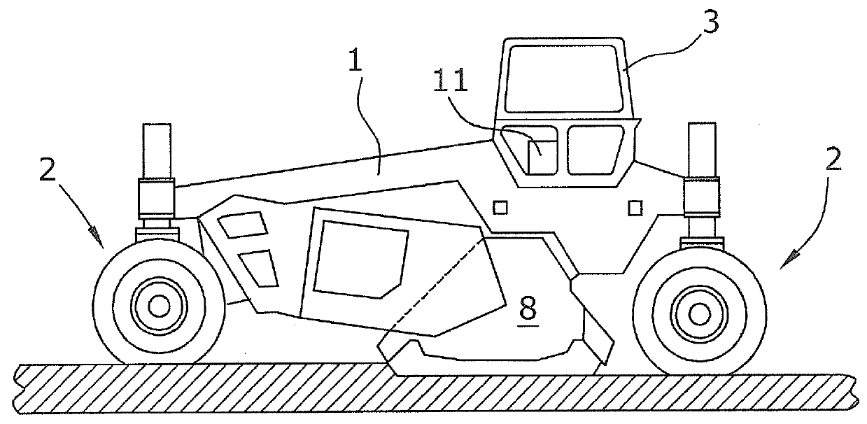
[0045]FIG. 1 shows an automotive device for working roadways, in particular a cold recycler or a soil stabilizer, with a machine frame 1 carried by wheels 2 and an operator's platform comprised of a driver's cabin 3. The wheels 2 may be driven individually and may alternatively also be replaced by crawler tracks.

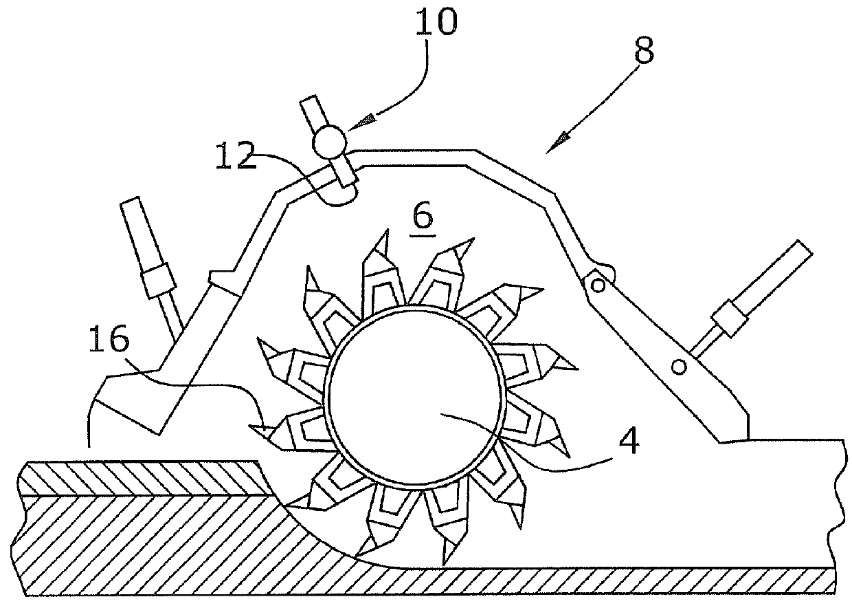
[0046]A working drum 4 is arranged underneath the machine frame 1 in a drum housing 8 which forms the boundary of the working chamber 6 of the working drum 4 towards the top and to the sides. A detailed description of the road construction machine shown in FIG. 1 can be inferred from WO-A96 / 24725 (U.S. Pat. No. 5,893,677), the details of which are incorporated herein by reference.

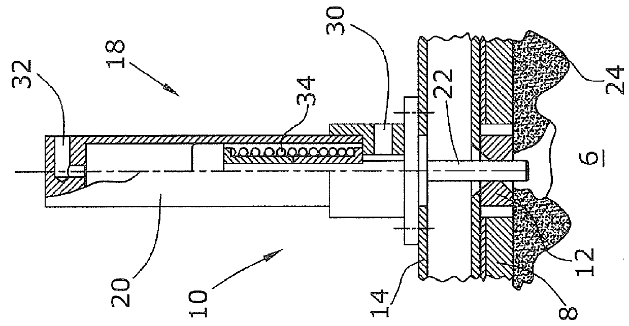
[0047]The drum housing 8 features a spraying device 10 in its upper section which can be used to inject, by means of several outlet nozzles 12 arranged preferably next to one another, for example, binding agents or water into the working chamber 6 and onto the working drum 4.

[0048]The binding agent ...


PUM


Abstract

In a device for working ground surfaces or roadways including a machine frame and a working drum in a drum housing arranged at said machine frame, where no less than one spraying device extending parallel to the working drum and featuring several outlet nozzles for spraying agents arranged next to one another and directed towards the working drum is arranged at the drum housing, where the outlet nozzles include one each drivable closing mechanism with a closing element which, in an open position, fully uncovers the nozzle channel of the outlet nozzle and, in a closed position, closes the nozzle channel, it is provided for the following features to be achieved: that a controller drives the closing mechanisms, with the outlet nozzles and the related closing elements being adapted to one another in such a fashion that the flow cross-section in the outlet nozzle is variable in accordance with the position of the closing element on a specified path between the open position and closed position.

Description

BACKGROUND OF THE INVENTION[0001]1. Field of the Invention[0002]The invention relates to a device, as well as a method for working ground surfaces or roadways.[0003]2. Description of the Prior Art[0004]The prior art includes, for example, EP 960 239 B1 (U.S. Pat. No. 6,565,281) or EP 1 396 581 A2 (U.S. Pat. No. 6,887,013).[0005]The known devices for working ground surfaces or roadways, such as soil stabilizers or recyclers, are provided with a working drum which breaks up and mixes ground surfaces or roadways. In the case of hard roadways consisting of asphalt or concrete, these are milled. The working drum is surrounded by a bell-shaped drum housing which encloses the working chamber of the working drum, where said working chamber serves as a mixing chamber for mixing the worked-off ground material with a spraying agent, such as hydraulic or bituminous binding agents (foamed bitumen, emulsions, or slurries), or water. Alternatively, binding agents (such as cement or lime) may also ...

Claims


Application Information

Patent Timeline
Patent Type & Authority Patents(United States)
IPC IPC(8): E01C23/00B05B13/00B05B12/12B05B1/30E01C19/17B05B15/02E01C23/088E01C21/00E01C23/06B05B15/522
CPCE01C19/176B05B1/3046B05B12/124B05B13/005B05B15/0233E01C21/00E01C23/00E01C23/065E01C23/088E21C47/00B05B15/5225E02D3/005E01C23/127
Inventor MENZENBACH, CHRISTOPHWALTERSCHEID, BERNDBARIMANI, CYRUSHAHN, GUNTER
Owner WIRTGEN GMBH
Features
  • R&D
  • Intellectual Property
  • Life Sciences
  • Materials
  • Tech Scout
  • Unparalleled Data Quality
  • Higher Quality Content
  • 60% Fewer Hallucinations
Learn More