Construction machine

a construction machine and air filter technology, applied in the direction of machines/engines, mechanical equipment, transportation and packaging, etc., can solve the problems of reducing the exhaust efficiency of the air, reducing the exhaust efficiency, and reducing the efficiency of the air exhaust, so as to improve the exhaust efficiency and efficiently collect the air flowing.

Active Publication Date: 2016-06-28
KOBELCO CONSTR MASCH CO LTD
View PDF17 Cites 124 Cited by
  • Summary
  • Abstract
  • Description
  • Claims
  • Application Information

AI Technical Summary

Benefits of technology

[0012]An object of the present invention is to provide a construction machine having an engine room, the control machine being capable of efficiently collecting air flowing in the engine room and improving exhaust efficiency. The construction machine includes: an engine room; an engine housed in the engine room; a heat exchanger provided at a first side as one side in a longitudinal direction of the engine; a fan of an axial-flow type provided at the first side of the engine and adapted to be rotated to generate, around the engine, a flow of cooling air which enters the engine room from an outside of the engine room and passes through the heat exchanger, the flow containing respective direction components in a rotational direction, a centrifugal direction, and an axial direction, of the fan; and an exhaust duct having an air inlet opening and an air outlet opening and provided in the engine room so as to extend in a fan axial direction parallel with a rotation axis of the fan along the engine, the exhaust duct adapted to guide the flow of the air so as to collect the air, which flows at a downstream side of the fan in the fan axial direction, in a region extending in the fan axial direction and so as to discharge the air to an outside of the engine room.

Problems solved by technology

The flow of air is therefore susceptible to large resistance and likely to form turbulence.
This involves a decrease in exhaust efficiency.
As a technique for solving this problem, Patent Documents 1 and 2 disclose providing a groove, that is, a concave path, vertically extending to a portion behind a fan in front of the counterweight 6 forming a rear surface of the engine room 8, and directly collecting air blown out from the fan 12 to directions including a swirling direction and a radial direction of the fan 12, through the groove, and discharging the air outside the engine room; however, this technique does not actually improve exhaust efficiency of the air for the following reason.
Furthermore, there is great airflow resistance in the inlet portion of the groove, which degrades air volume performance.

Method used


Image

  • Construction machine
  • Construction machine
  • Construction machine

Examples


first embodiment

[0027]Next are described details of the present invention with reference to FIGS. 1 to 6.

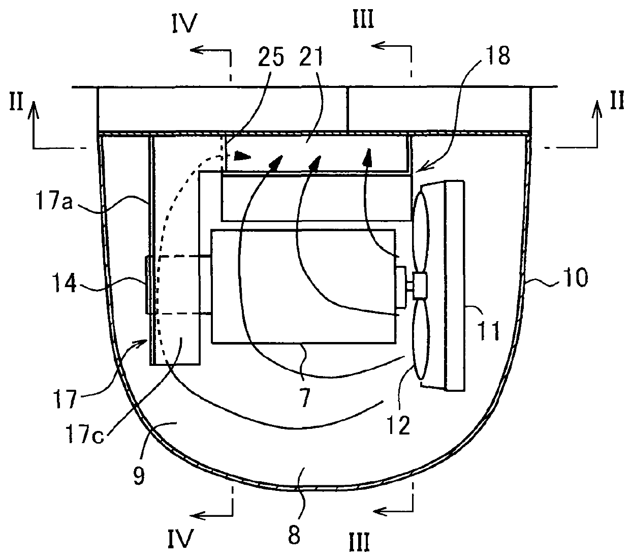
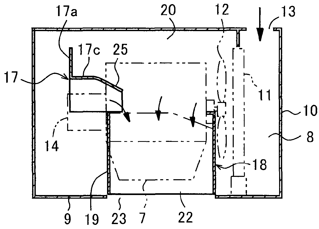
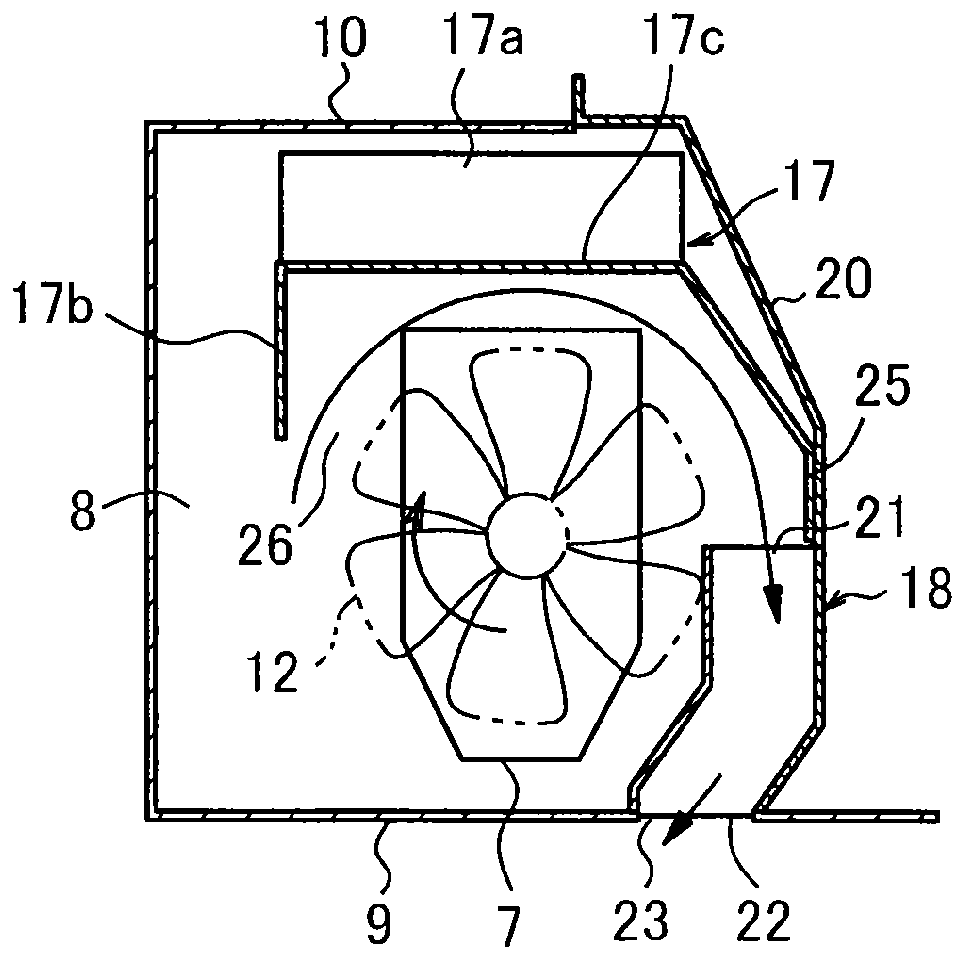
[0028]The excavator according to the first embodiment includes an exhaust duct 18 in addition to the above configuration elements. The exhaust duct 18 is provided at a front lower part of the engine 7 in the engine room 8, in a posture extending in a fan axial direction (a right and left direction of the excavator) along the engine 7. The exhaust duct 18 is composed of a duct body 19 and a partition plate 20 which is located in front of the engine 7. The partition plate 20 is one of partition members that partition a space above the upper frame 3 into front and rear portions to thereby define the engine room 8 at a rear part of the upper frame 3. The partition plate 20 is provided to stand up on the bottom plate 9 at a position in front of the engine 7, extending in a right and left direction over substantially a whole region in the left and right direction of the bottom plate 9.

[0029]As shown i...

second embodiment

[0044]the present invention will be described with reference to FIGS. 7 and 8. The second embodiment, while being based on the excavator according to the first embodiment, includes an exhaust duct 27 in place of the exhaust duct 18. Differently from the exhaust duct 18, the exhaust duct 27 is configured as an independent housing that encloses an interior space, which is long in right and left direction, by only the exhaust duct 27 itself, while, similar to the exhaust duct 18, the exhaust duct 27 is installed in a posture extending in a right and left direction in front of the engine 7 in the engine room 8. The exhaust duct 27 has a shape that is bent in a front and rear direction at vertically arranged two positions so that upper and lower part of the exhaust duct 27 direct obliquely backward, that is, so that a vertically intermediate part thereof swells to the front as compared with the upper and lower ends. Thus, the exhaust duct 27 has a shape of more fitting the swirling direc...


PUM


Abstract

In a construction machine having an engine room and capable of efficiently collecting air flowing in the engine room, a heat exchanger provided at a first side of the engine, and a fan provided at the first side and rotating to generate around the engine a flow of cooling air, further includes an exhaust duct extending in a fan axial direction parallel with a rotation axis of the fan along the engine. The exhaust duct guides the flow of the air to collect the air flowing downstream of the fan in the fan axial direction, in a region extending in the fan axial direction, and discharges the air to an outside of the engine room.

Description

TECHNICAL FIELD[0001]The present invention relates to a construction machine, such as an excavator, the construction machine including a heat exchanger and a device for cooling the heat exchanger.BACKGROUND ART[0002]A background art of the present invention will be described by taking an excavator shown in FIG. 9 as an example.[0003]The excavator includes a lower traveling body 1, an upper swirling body 2 mounted pivotally thereon and having an upper frame 3 as a base, various facilities and equipment including a cabin 4 mounted on the upper frame 3, a working attachment (or a excavation attachment) 5 attached to a front part of the upper frame 3, and a counterweight 6 attached to a rear end part of the upper frame 3. The cabin 4 is provided at a left-side front part in a traveling direction of the upper frame 3. An engine room 8 which houses the engine 7 is provided at a rear part of the upper frame 3.[0004]FIG. 10 is a schematic cross-sectional view of arrangement of equipment and...

Claims


Application Information

Patent Timeline
Patent Type & Authority Patents(United States)
IPC IPC(8): F01P1/02B60K11/06F01P5/06E02F9/08F01P1/00
CPCE02F9/0866B60K11/06F01P1/02F01P5/06B60Y2200/412F01P2001/005
Inventor NUMASAWA, MASARU
Owner KOBELCO CONSTR MASCH CO LTD
Why Eureka
Try Eureka