Method for drilling at least one hole into a workpiece

a workpiece and hole technology, applied in the direction of abrasion apparatus, metal working apparatus, manufacturing tools, etc., can solve the problems of difficult drilling into workpieces, electrical discharge machining, damage to sensitive layers, etc., and achieve the effect of reducing the risk of wall damag

Active Publication Date: 2016-07-05
WATERJET ROBOTICS
View PDF25 Cites 11 Cited by
  • Summary
  • Abstract
  • Description
  • Claims
  • Application Information

AI Technical Summary

Benefits of technology

[0007]It is an object of the present invention to provide a method and a machining arrangement for drilling at least one hole into a workpiece having wall sections disposed behind one another by way of a liquid machining jet, wherein the method and the machining arrangement can be used for a variety of workpiece geometries and substantially prevent undesirable wall damage.
[0009]This allows economical drilling of the hole. If the penetration is made by way of a pulsed machining jet, the drilling can be terminated in a timely fashion, and damage to the wall section arranged behind the drilled wall section, as seen looking in the drilling direction, can be substantially avoided. Moreover, a drilling direction is possible which points from the outer side of the workpiece to the inside, so that the method can be used for a variety of workpiece geometries and drilling directions.
[0011]So as to reduce the risk of wall damage even further, a free-flowing protective agent, which is for instance also used to generate the machining jet, is preferably used to fill the workpiece and / or a sensor device is used to detect the time at which the machining jet penetrates the front wall section.

Problems solved by technology

Drilling into a workpiece is difficult, among other things, when the same has one or more cavities or, generally speaking, wall sections, which are arranged offset behind one another.
These methods have the disadvantage that the material ablation takes place by heat development, which may result in undesirable damage to sensitive layers.
Electrical discharge machining has the further disadvantage that it can only be used for conductive workpieces.
This method has the disadvantage that it can only be used for special geometries of workpieces and holes.
Drilling is in particular not possible when the cavity is not accessible to the machining head and / or the drilling direction is oriented perpendicularly to the workpiece surface, for example.
Thus, it is difficult to stop the impact of the jet precisely when it penetrates the workpiece.
The disclosed method is not suitable to drill holes in a workpiece such that undesirable damages are prevented.

Method used


Image

  • Method for drilling at least one hole into a workpiece
  • Method for drilling at least one hole into a workpiece
  • Method for drilling at least one hole into a workpiece

Examples


Embodiment Construction

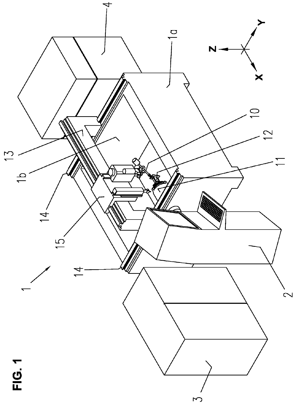
[0023]The machining device 1 comprises a machining head 10, from which a machining jet exits during operation, and a holding device 11 for holding a workpiece 12. In the present exemplary embodiment, the machining device 1 is configured to generate a machining jet made of a liquid containing or not containing abrasive material. For example, water is suitable as the liquid, and the abrasive material is sand, for example. Other media are also possible as the liquid, for example oil. Furthermore, it is conceivable to add one or more admixtures to the liquid, for instance polymers, to improve the efficacy of the machining jet.

[0024]The machining device 1 further comprises a basin 1b, which is delimited by walls 1a and in which the holding device 11 together with the workpiece 12 is disposed and into which the machining head 10 protrudes.

[0025]The operating device 2 comprises units for outputting and / or inputting information, such as a keyboard, monitor and / or pointing device. The contro...


PUM

PropertyMeasurementUnit
angleaaaaaaaaaa
angleaaaaaaaaaa
switching time tUaaaaaaaaaa

Abstract

The method is used to drill at least one hole into a front wall section of a workpiece (12) by way of a machining jet formed from liquid, to which abrasive material is admixed as needed. As seen looking in the drilling direction, the front wall section is located in front of a rear wall section of the workpiece, which is disposed with an intermediate space at a distance from the front wall section. The hole is drilled at least partially by the machining jet impinging on the front wall section in a pulsed manner. This pulsed jet is generated by the recurrent interruption of the impingement of the liquid and / or of the abrasive material on the front wall section.

Description

BACKGROUND OF THE INVENTION[0001]The present invention relates to a method for drilling at least one hole into a workpiece.[0002]Drilling into a workpiece is difficult, among other things, when the same has one or more cavities or, generally speaking, wall sections, which are arranged offset behind one another. The rear wall section, as seen looking in the drilling direction, for example, impairs drilling in the front wall section. In addition, measures must be taken which prevent damage to this wall section when the penetration is made in the front wall section. Workpieces that are this difficult to drill exist in the form of turbine blades, for example, in which a plurality of holes are to be provided for cooling.[0003]It is known to drill holes into such workpieces by way of laser or electrical discharge machining (see, for example, U.S. Pat. No. 7,041,933 B1). These methods have the disadvantage that the material ablation takes place by heat development, which may result in unde...

Claims


Application Information

Patent Timeline
Patent Type & Authority Patents(United States)
IPC IPC(8): B26F1/26B24C7/00B26F3/00B24C1/04
CPCB26F1/26B24C1/045B24C7/0015B26F3/004B26F3/008B23B35/00
Inventor MAURER, WALTER
Owner WATERJET ROBOTICS
Why Eureka
Try Eureka