Directional coupler

a directional coupler and wideband technology, applied in coupling devices, electrical devices, waveguides, etc., can solve the problems of inability to wideband, disadvantageous increase of the size of the directional coupler, and difficulty in reducing the signal reflection at the coupling port, so as to reduce the size of the signal reflection

Active Publication Date: 2016-07-05
TDK CORPARATION
View PDF5 Cites 13 Cited by
  • Summary
  • Abstract
  • Description
  • Claims
  • Application Information

AI Technical Summary

Benefits of technology

[0014]It is an object of the present invention to provide a directional coupler that is wideband capable without being increased in size, and is able to reduce signal reflection at the coupling port where the coupling port is connected with a signal source having an output impedance equal to the resistance of a terminator connected to the terminal port.
[0020]According to the directional coupler of the present invention, where a combination of the first coupling line section and a portion of the main line to be electromagnetically coupled to the first coupling line section is referred to as the first coupling section, a signal path passing through the first coupling section and the low-pass filter is formed between the input port and the coupling port. The attenuation of a signal as it passes through the low-pass filter varies according to the frequency of the signal. It is thus possible to suppress a change in the coupling of the directional coupler in response to a change in the frequency of the high frequency signal received at the input port. Further, in the directional coupler of the present invention, the low-pass filter includes the resistor connecting the aforementioned other end of the first capacitor to the ground. This makes it possible to reduce, with a simple configuration, signal reflection at the coupling port where the coupling port is connected with a signal source having an output impedance equal to the resistance of the terminator connected to the terminal port. Consequently, according to the present invention, it is possible to realize a directional coupler that is wideband capable without being increased in size and is able to reduce signal reflection at the coupling port where the coupling port is connected with a signal source having an output impedance equal to the resistance of a terminator connected to the terminal port.

Problems solved by technology

The conventional directional coupler therefore suffers from the problem of not being wideband capable.
Further, for a directional coupler including a low-pass filter such as that disclosed in each of the above two U.S. publications, it is difficult to reduce signal reflection at the coupling port by simply adjusting the inductance of the inductor constituting the low-pass filter and the capacitance of the capacitor constituting the low-pass filter.
The need for the two low-pass filters and the two terminators disadvantageously increases the size of the directional coupler.

Method used


Image

  • Directional coupler
  • Directional coupler
  • Directional coupler

Examples


first embodiment

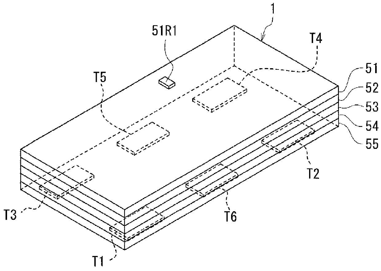
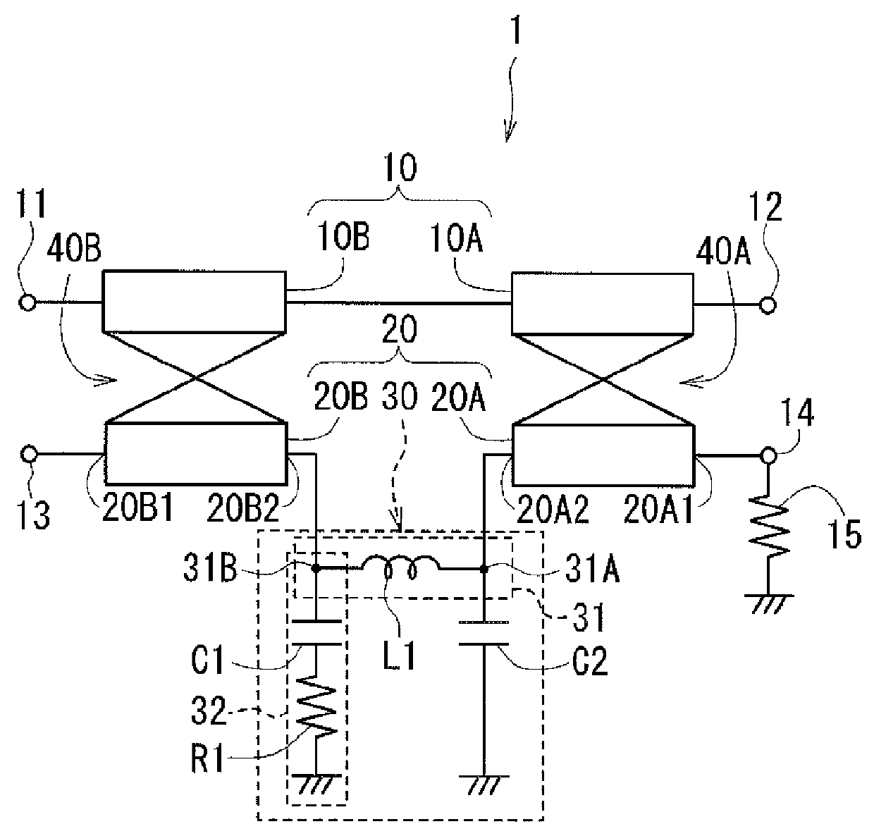
[0045]Preferred embodiments of the present invention will now be described in detail with reference to the drawings. First, reference is made to FIG. 1 to describe the circuit configuration of a directional coupler according to a first embodiment of the invention. As shown in FIG. 1, the directional coupler 1 according to the first embodiment includes an input port 11, an output port 12, a coupling port 13, and a terminal port 14. The directional coupler 1 further includes a main line 10 connecting the input port 11 and the output port 12, and a subline 20 connecting the coupling port 13 and the terminal port 14. The terminal port 14 is grounded via a terminator 15. More specifically, one end of the terminator 15 is connected to the terminal port 14 and the other end thereof is connected to the ground. In the first embodiment, the terminator 15 has a resistance of 50Ω.

[0046]The subline 20 includes a first coupling line section 20A, a second coupling line section 20B, and a low-pass ...

second embodiment

[0081]A directional coupler 1 according to a second embodiment of the invention will now be described with reference to FIG. 12. FIG. 12 is a circuit diagram showing the circuit configuration of the directional coupler 1 according to the second embodiment. In the directional coupler 1 according to the second embodiment, the low-pass filter 30 is configured differently than the first embodiment.

[0082]In the second embodiment, the low-pass filter 30 includes a first path 31, a second path 32 and a second capacitor C2 as in the first embodiment. The first path 31 has a third end 31A and a fourth end 31B opposite to each other. The third end 31A is connected to the second end 20A2 of the first coupling line section 20A. The first path 31 includes at least one inductor provided between the third end 31A and the fourth end 31B. In the second embodiment the first path 31 includes, as the at least one inductor, a first inductor L11 and a second inductor L12 connected in series. The second p...

third embodiment

[0089]A directional coupler 1 according to a third embodiment of the invention will now be described with reference to FIG. 16. FIG. 16 is a circuit diagram showing the circuit configuration of the directional coupler 1 according to the third embodiment. In the directional coupler 1 according to the third embodiment, the subline 20 includes the first coupling line section 20A and the low-pass filter 30 but does not include the second coupling line section 20B. The main line 10 includes the first portion 10A but does not include the second portion 10B. Further, the directional coupler 1 according to the third embodiment includes the first coupling section 40A but does not include the second coupling section 40B.

[0090]The low-pass filter 30 of the third embodiment may have the same configuration as that of the first or second embodiment. FIG. 16 illustrates the case where the low-pass filter 30 has the same configuration as that of the first embodiment. In the third embodiment, the fo...


PUM


Abstract

A directional coupler includes a main line and a subline. The main line connects an input port and an output port. The subline connects a coupling port and a terminal port. The subline includes a first coupling line section connected to the terminal port, a second coupling line section connected to the coupling port, and a low-pass filter. The low-pass filter includes an inductor provided between the first and second coupling line sections, a first capacitor having an end connected to the connection point between the inductor and the second coupling line section, a resistor connecting the other end of the first capacitor to the ground, and a second capacitor connecting the connection point between the inductor and the first coupling line section to the ground.

Description

BACKGROUND OF THE INVENTION[0001]1. Field of the Invention[0002]The present invention relates to a wideband capable directional coupler.[0003]2. Description of the Related Art[0004]Directional couplers are used for detecting the levels of transmission / reception signals in transmission / reception circuits of wireless communication apparatuses such as cellular phones and wireless LAN communication apparatuses.[0005]A directional coupler configured as follows is known as a conventional directional coupler. The directional coupler has an input port, an output port, a coupling port, a terminal port, a main line, and a subline. The main line has a first end connected to the input port and a second end connected to the output port. The subline has a first end connected to the coupling port and a second end connected to the terminal port. The main line and the subline are configured to be electromagnetically coupled to each other. The terminal port is grounded via a terminator having a resis...

Claims


Application Information

Patent Timeline
Patent Type & Authority Patents(United States)
IPC IPC(8): H01P5/18H01P3/08
CPCH01P5/187
Inventor OHASHI, TAKESHIMITAKE, YUKIO
Owner TDK CORPARATION
Why Eureka
Try Eureka