Memory card connector having several conductive plastic parts with different values of resistance for discharging static electricity

a technology of static electricity and memory card connectors, which is applied in the direction of sensing record carriers, coupling device connections, instruments, etc., can solve the problems of terminal damage, electrical charge that builds up in the card, and at least the presence of electricly charged cards, so as to simplify the design of the connector, extend the service life of the inserted cards, and facilitate the manufacturing of the memory card connectors

Active Publication Date: 2016-07-12
BANKS & ACQUIRERS INT HLDG
View PDF19 Cites 1 Cited by
  • Summary
  • Abstract
  • Description
  • Claims
  • Application Information

AI Technical Summary

Benefits of technology

[0017]Thus, the invention makes it possible to avoid the addition of metal discharge zones which have an abrasive effect on the cards that are inserted into the memory connector.

Problems solved by technology

At the same time, these novel cards have new drawbacks: these cards, known as new generation cards, tend to get electrically charged to a far greater extent than do the earlier cards.
Now, electrically charged cards present at least one problem: the electrical charge that builds up in the card must be discharged at some time or other.
In the former case, the terminal can be seriously damaged.
In the latter case, it is the card that can be damaged.
If the part through which the current passes (the chip of the card, the terminal) is sensitive to these intensities, then the terminal and / or the card can be damaged.
This operation is also complex since it requires the creation of several metal elements on the basis of an existing memory card connector.
Now, the creation of such mechanical elements is complex and costly.
However, although they theoretically resolve the problem of removing charge, these prior-art solutions raise yet other problems.
Firstly, in the case of the integrated solution, the designing of the memory card connector is complex.
This mounting operation is costly.
Furthermore, another problem common to both prior-art solutions is linked to the fact that the metal pins could damage the card when it is withdrawn.
Indeed, the metal pins are abrasive parts that rub the card with varying degrees of intensity.
Now, by being continually rubbed, a card can be damaged.
In short, in the prior-art solutions, the contact is made with relatively low resistance and the addition of a resistor in a series connection takes up a great deal of space.
This causes the current of the discharge to remain high and can therefore create damage to sensitive components.
Although these zones are numerous, this does not make it possible to cover each and every smartcard configuration.
Finally, the basic solution of adding a strip (the corrective solution) requires the addition of an additional part, and this generates costs.
Thus, the existing solutions are not satisfactory and novel solutions without the drawbacks of the prior-art solutions need to be proposed.

Method used


Image

  • Memory card connector having several conductive plastic parts with different values of resistance for discharging static electricity
  • Memory card connector having several conductive plastic parts with different values of resistance for discharging static electricity
  • Memory card connector having several conductive plastic parts with different values of resistance for discharging static electricity

Examples


first embodiment

6.2.1 First Embodiment

[0036]In a first embodiment, the memory card connector is equipped with a specific, relatively conductive part connected to the ground of the terminal. The resistance of this part is relatively low (of the order of a few hundreds of ohms). This is a configuration requiring little investment in terms of design. All that is necessary is to build a part that gets fixed to the memory card connector. This part is connected to the ground of the terminal.

[0037]In this first embodiment, the part can be either over-molded or mounted subsequently (in the latter case, the material used does not need to have a very high temperature performance since it is not mounted on the surface of the printed circuit).

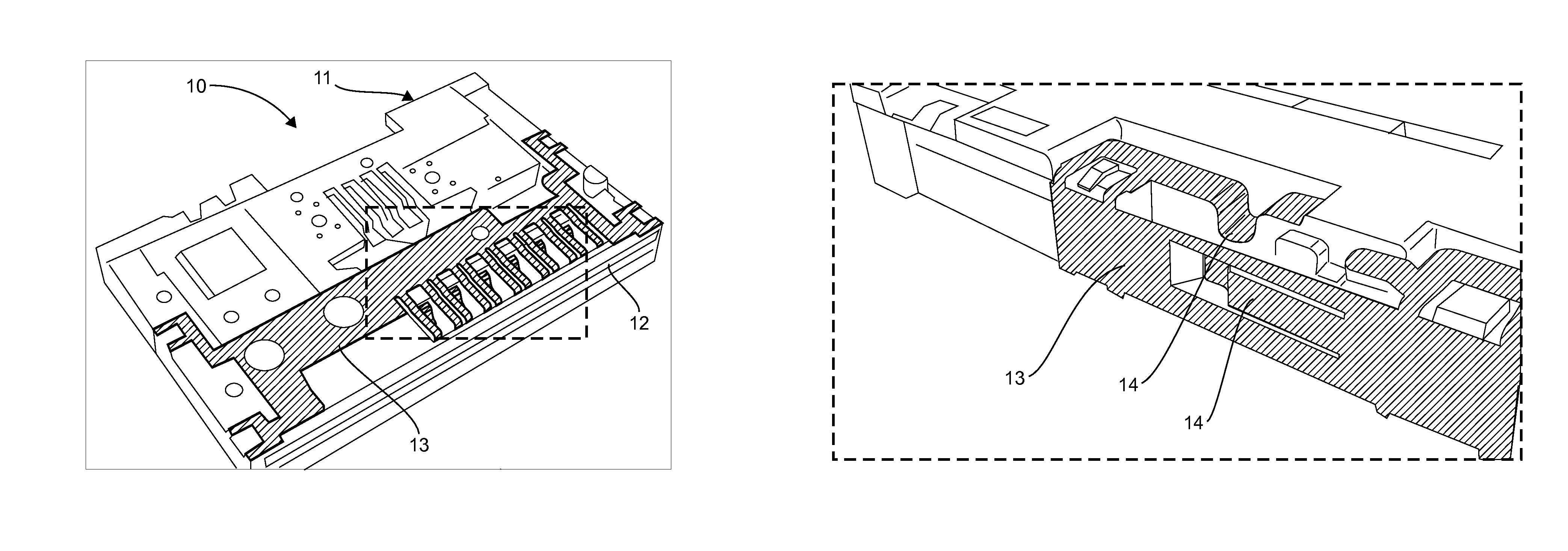
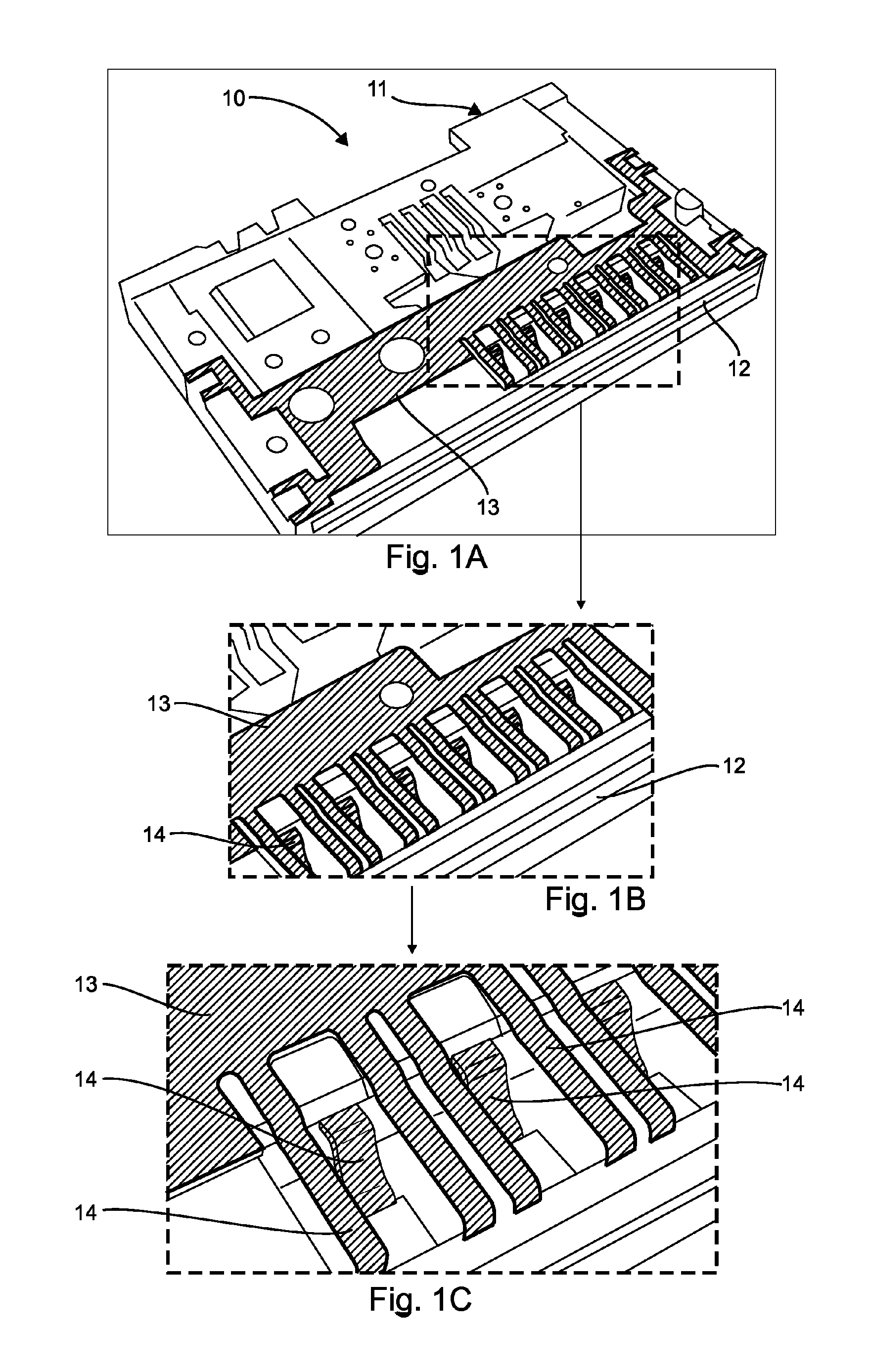
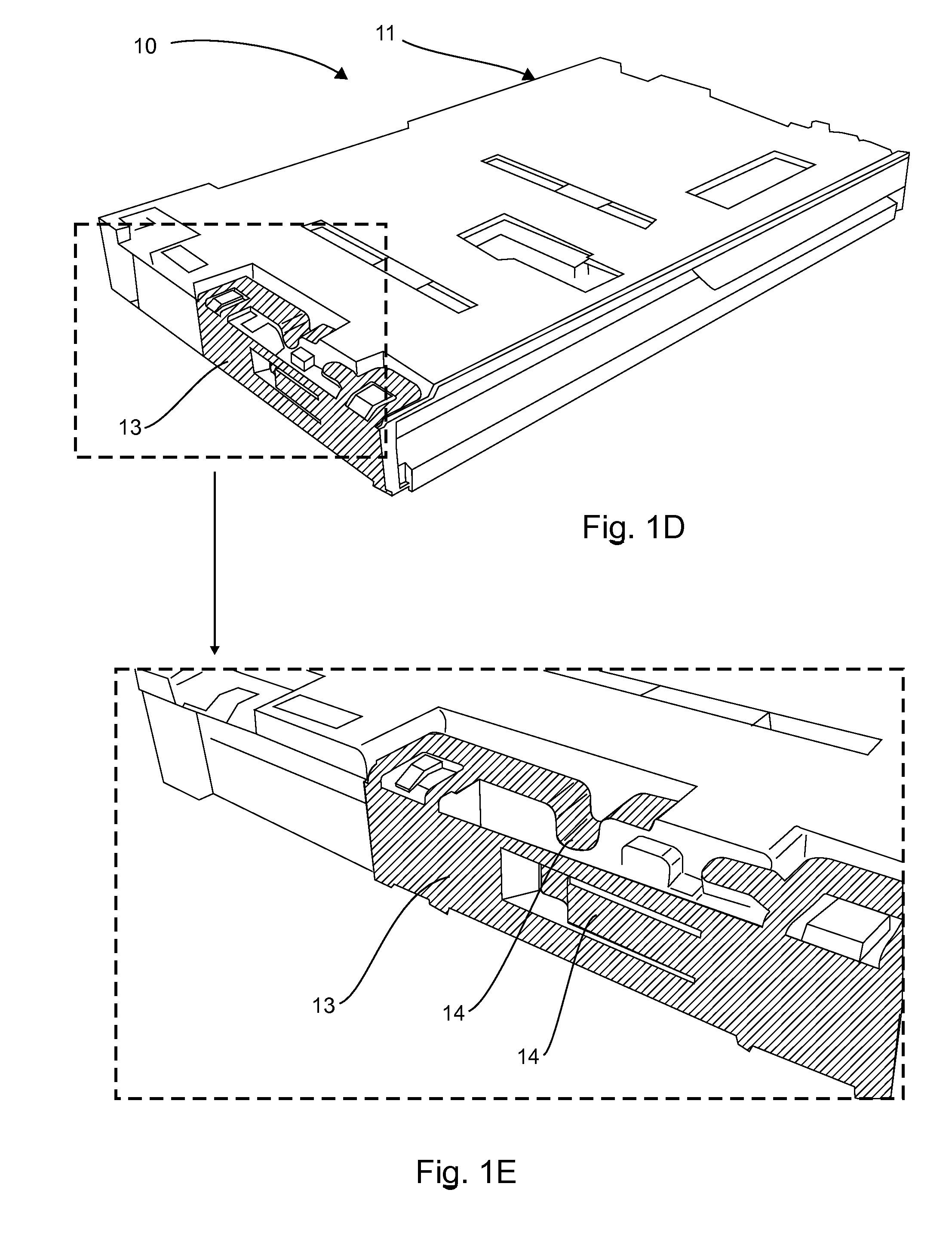
[0038]Referring to FIG. 2, we present a first embodiment of a portion of a connector for a memory card according to the invention.

[0039]The memory card connector 20 comprises an insertion module 21 with a generally rectangular parallelepiped shape. This insertion module 2...

second embodiment

6.2.2 Second Embodiment

[0042]In this second embodiment, it is the memory card connector that is fully made out of conductive material but at a very low level of conduction (the surface resistance of the material should be of the order of 105 to 106 Ω / square).

[0043]Whether it is in the first or second embodiment, it is proposed to make parts out of one of the following known materials:[0044]SABIC Innovative Plastics LNP Stat-kon REP349 PA 66 (1.00e+7 to 1.00e+9 ohm / cm in values of volume resistance);[0045]SABIC Innovative Plastics LNP Stat-kon LX04420C PEEK (1.00e+6 to 1.00e+8 ohm / cm in value of volume resistance);[0046]Cool Polymers Coolpoly® D5502 Thermally Conductive Liquid Crystalline Polymer (1.00e+14 ohm / cm 1.00e+14 ohm / cm in value of volume resistance).

[0047]In the second embodiment, the material in addition to having these electrical characteristics must withstand a re-melting temperature and wear and tear associated with the rubbing of the cards.

third embodiment

6.2.3 Third Embodiment

[0048]In this embodiment, the discharge is carried out by the use of several parts made out of conductive plastic. The advantage of this embodiment is that it enables a gradual and non-aggressive discharge of the card. In this embodiment, the memory card connector comprises a plurality of parts made out of conductive plastic, each part made out of conductive plastic having a different surface resistance.

[0049]In one particular implementation of this embodiment, a first part positioned at the inlet to the memory card connector has a surface resistance of the order of 1012 Ω / square. A second part positioned inside the memory card connector has a surface resistance of the order of 1010 Ω / square. This second part comes into contact with the card after the discharging carried out by the first part. A third part, positioned inside the memory card connector, has a surface resistance of the order of 108 Ω / square.

[0050]This third part comes into contact with the card su...


PUM


Abstract

A connector is provided for memory card including an insertion module of an overall right-angle parallelepipedal shape. The insertion module includes an insertion slot for inserting a memory card. The connector furthermore includes several static electricity discharge zones coming into contact with a portion of a surface of a memory card upon the insertion of the memory card into the memory card connector. Each of the static electricity discharge zones is made at least in part of a conducting plastic material having a different surface resistance value, so that the discharge of the card is effected progressively in several phases.

Description

1 CROSS-REFERENCE TO RELATED APPLICATIONS[0001]This Application is a Section 371 National Stage Application of International Application No. PCT / EP2013 / 062791, filed Jun. 19, 2013, the content of which is incorporated herein by reference in its entirety, and published as WO 2013 / 190006 on Dec. 27, 2013, not in English.2 FIELD OF THE INVENTION[0002]The invention relates to a memory card connector also called an MC connector. A memory card connector is a device enabling the insertion of a memory card. A memory card connector is generally an element comprising a memory card reader terminal. A memory card reader terminal can be, for example, a payment terminal. It can also be a personal digital assistant or again a communications terminal such as a cell phone or a Smartphone.3 PRIOR ART[0003]There are known memory card connectors for receiving a memory card. The card for example may be, for example, a smartcard which can be a payment card. Payment cards are cards that incorporate means ...

Claims


Application Information

Patent Timeline
Patent Type & Authority Patents(United States)
IPC IPC(8): H01R4/58G06K7/00H01R13/648
CPCH01R13/6485G06K7/0082
Inventor PAVAGEAU, STEPHANEGARY, DIDIER
Owner BANKS & ACQUIRERS INT HLDG
Why Eureka
Try Eureka