Surface acoustic wave filter on a lithium niobate substrate

a lithium niobate and surface acoustic wave technology, applied in the direction of impedence networks, electrical equipment, etc., can solve the problems of a smaller achievable bandwidth and a lower loss of filters, and achieve the effect of reducing the temperature dependency of the resonance frequency of the saw filter and the temperature dependence of the temperature dependency

Active Publication Date: 2016-07-12
SNAPTRACK
View PDF37 Cites 1 Cited by
  • Summary
  • Abstract
  • Description
  • Claims
  • Application Information

AI Technical Summary

Benefits of technology

[0015]The SAW filter is constructed to maximize the coupling which is directly linked to the relative bandwidth, to maximize the reflection coefficient and to minimize the propagation loss. However, these objects contradict each other and cannot be reached at the same time by a single embodiment so that a good trade off needs to be found that provides a SAW filter with sufficiently high coupling, sufficiently high reflection coefficient and sufficiently low propagation loss. Definitions of coupling and reflection coefficient are given later. The propagation loss describes the amount of the signal that gets lost when the signal propagates through the filter.
[0022]The electrode geometry is defined by the electrode thickness and the metallization ratio. The range given for these two electrode geometry parameters and for the substrate cut angle provides a good tradeoff between insertion loss and maximum reachable bandwidth of the filter.
[0024]In one embodiment, the filter comprises two acoustic tracks arranged in a cascade. Each acoustic track can be composed of multiple interdigital transducers with acoustic cavities in-between different transducers. The acoustic cavities can be “filled” by metalized stripes that are not part of the transducers. A metalized stripe at the surface of the substrate prevents the surface wave from entering into the substrate. Further, the metallization helps to adjust the velocity of the wave in the areas that are not covered by an IDT to the velocity in the areas covered by an IDT.
[0026]In one embodiment, the SAW filter and its metallization structures are covered by a temperature compensation layer and / or a protection layer. This temperature compensation layer helps to reduce the temperature dependency of the resonance frequency of the SAW filter. An SiO2 layer can be chosen as temperature compensation layer and placed on the filter as SiO2 has an opposite temperature dependency compared to the piezoelectric material. A protection layer can serve to protect the electrodes from corrosion or from shorting due to metallic particles which may be present in the package.

Problems solved by technology

These filters have a lower loss than the filters disclosed by U.S. Pat. No. 5,729,186 but with the drawback of a smaller achievable bandwidth.

Method used


Image

  • Surface acoustic wave filter on a lithium niobate substrate
  • Surface acoustic wave filter on a lithium niobate substrate
  • Surface acoustic wave filter on a lithium niobate substrate

Examples


Embodiment Construction

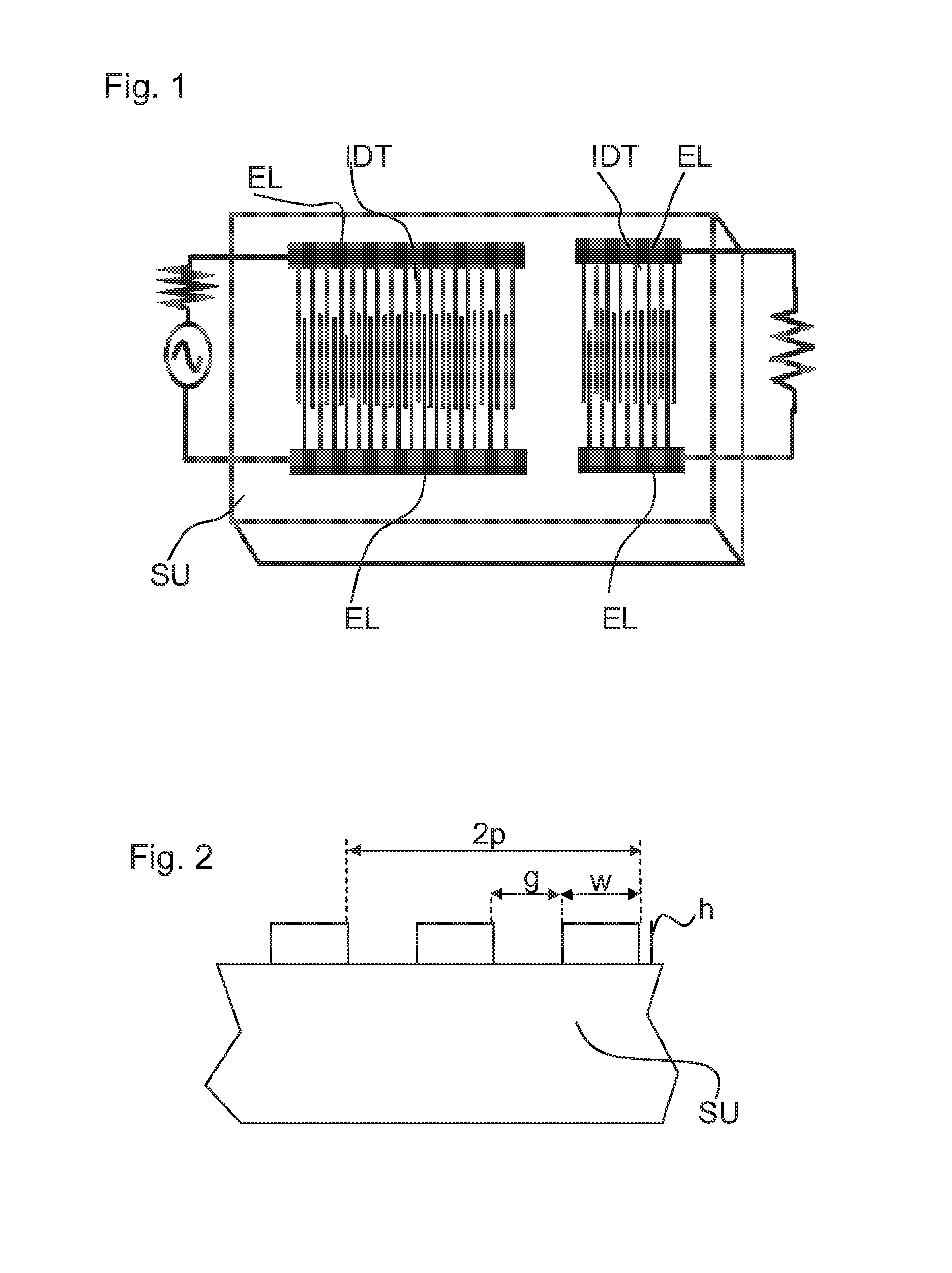
[0048]FIG. 1 is a schematic view showing a surface acoustic wave filter according to the present invention. FIG. 2 is a portion of a cross-sectional view of the SAW filter.

[0049]The SAW filter comprises a piezoelectric substrate SU. The substrate SU is lithium niobate. Further, two interdigital transducers IDT are placed on the substrate SU. The first transducer IDT transforms a high-frequency signal applied to its electrodes into a surface acoustic wave. The second transducer IDT transforms the surface acoustic wave back to a high-frequency signal thereby selectively extracting a desired frequency band.

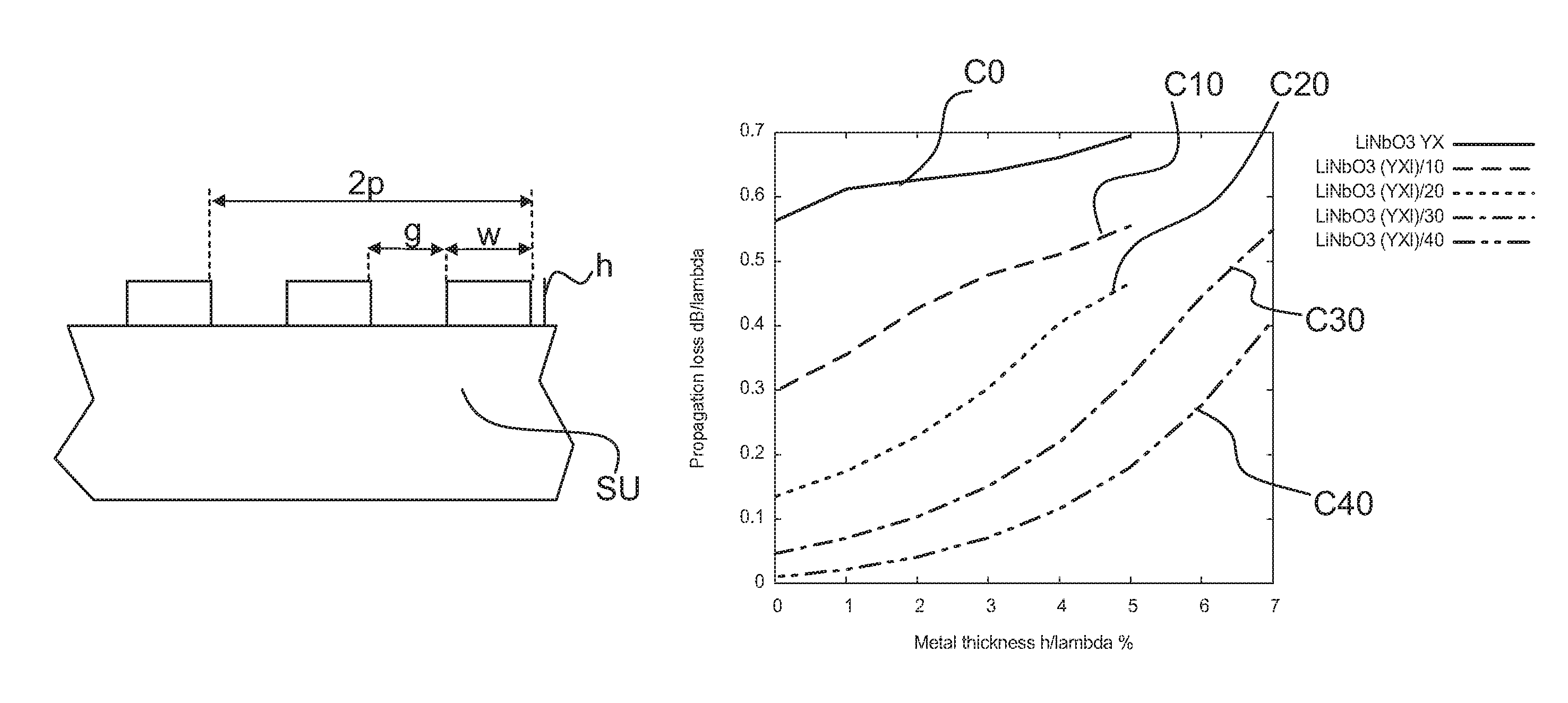
[0050]Each transducer IDT comprises two electrodes EL wherein the fingers of the electrodes overlap each other on an acoustic track. The width of a finger is given by w. The gap width between two fingers is given by g. Further, the thickness of a finger is given by h. An SAW filter as shown in FIGS. 1 and 2 excites a surface acoustic wave with a wavelength λ. In a normal finger arran...


PUM


Abstract

A surface acoustic wave filter includes a θ-rotated Y-cut X-propagation lithium niobate substrate. The cut angle ranges from 20° to 40°. An interdigital transducer can be used for exciting a surface acoustic wave that is formed on the substrate.

Description

[0001]This patent application is a national phase filing under section 371 of PCT / EP2011 / 050897, filed Jan. 24, 2011, which is incorporated herein by reference in its entirety.TECHNICAL FIELD[0002]The present invention concerns a surface acoustic wave (SAW) filter that can excite a surface acoustic wave on a substrate of piezoelectric material and selectively extract a desired frequency band.BACKGROUND[0003]SAW filters can be used in high-frequency circuits, e.g., in a bandpass filter. A SAW filter comprises a piezoelectric material and an electrode structure. The electrodes can transform a high-frequency signal into an acoustic wave which propagates along the surface of the piezoelectric material. Further, a second electrode structure is arranged to transform the acoustic wave back into a high-frequency signal thereby selectively extracting a desired frequency band.[0004]SAW filters can be used as part of a front-end module of a mobile phone. There is a need to reduce the overall c...

Claims


Application Information

Patent Timeline
Patent Type & Authority Patents(United States)
IPC IPC(8): H03H9/64H03H9/02
CPCH03H9/64H03H9/02559H03H9/02755H03H9/02834H03H9/6433H03H9/6463
Inventor CHAMALY, STEPHANEFONG, HOI YAN ANNA
Owner SNAPTRACK
Why Eureka
Try Eureka