Negative gauge pressure dynamic convection system for artificial limb and associated methods

a dynamic convection and negative gauge technology, applied in the field of artificial limbs, can solve the problems of increasing skin temperature, increasing moisture accumulation, increasing the accumulation of perspiration between the liner and the limb, etc., and achieve the effect of reducing the amount of perspiration generated

Active Publication Date: 2016-07-26
KING CHARLES RUSSELL
View PDF37 Cites 9 Cited by
  • Summary
  • Abstract
  • Description
  • Claims
  • Application Information

AI Technical Summary

Benefits of technology

[0006]In view of the foregoing background, it is therefore an object of the present invention to provide an artificial limb system and a method to manage excessive thermal buildup and consequently reduce the amount of perspiration generated.
[0008]The limb-conformable thermal convection liner is used for both suspension and comfort. It has longitudinal scallops or convection guides on its exterior surface that taper proximally. Its interior surface has airflow grooves to improve internal airflow efficiency. The liner may be constructed from thermally conductive silicone and its textile cover may contain phase change yarns.
[0016]The provided limb-conformable thermal convection liner is used for both suspension and comfort. It has longitudinal scallops on its exterior surface that taper proximally. Its interior surface has airflow grooves to improve internal airflow efficiency. The liner may be constructed from thermally conductive silicone and the yarns of its cover may contain phase change materials. The provided artificial limb socket may be manufactured from carbon fiber or thermoplastic, for example. It has an affixed over-molded enclosure for system components such as a battery housing, control circuits, airflow generating device, negative gauge pressure regulating device and configured for associated ports and tubing.
[0020]The many embodiments of the present invention described herein contribute to providing thermal energy transfer (convection) from within an artificial limb to the ambient atmosphere, which directly reduces the amount of perspiration generated.

Problems solved by technology

(2001) in an article titled “Moisture permeability of the total surface bearing prosthetic socket with a silicone liner: is it superior to the patella-tendon bearing prosthetic socket?” J. Uoeh, 23, 225-32 found that an artificial limb liner seals off airflow to both the residual limb and to the prosthetic socket, which results in an accumulation of perspiration between the liner and limb.
It can be extrapolated from the citations above that a wearing a prosthetic limb will result in an increasing rise in skin temperature and increasing moisture accumulation.

Method used


Image

  • Negative gauge pressure dynamic convection system for artificial limb and associated methods
  • Negative gauge pressure dynamic convection system for artificial limb and associated methods
  • Negative gauge pressure dynamic convection system for artificial limb and associated methods

Examples


Embodiment Construction

[0038]The present invention will now be described more fully hereinafter with reference to the accompanying drawings in which preferred embodiments of the invention are shown. This invention may, however, be embodied in many different forms and should not be construed as limited to the embodiments set forth herein. Rather, these embodiments are provided so that this disclosure will be thorough and complete, and will fully convey the scope of the invention to those skilled in the art. Like numbers refer to like elements throughout. The dimensions of layers and regions may be exaggerated in the figures for greater clarity.

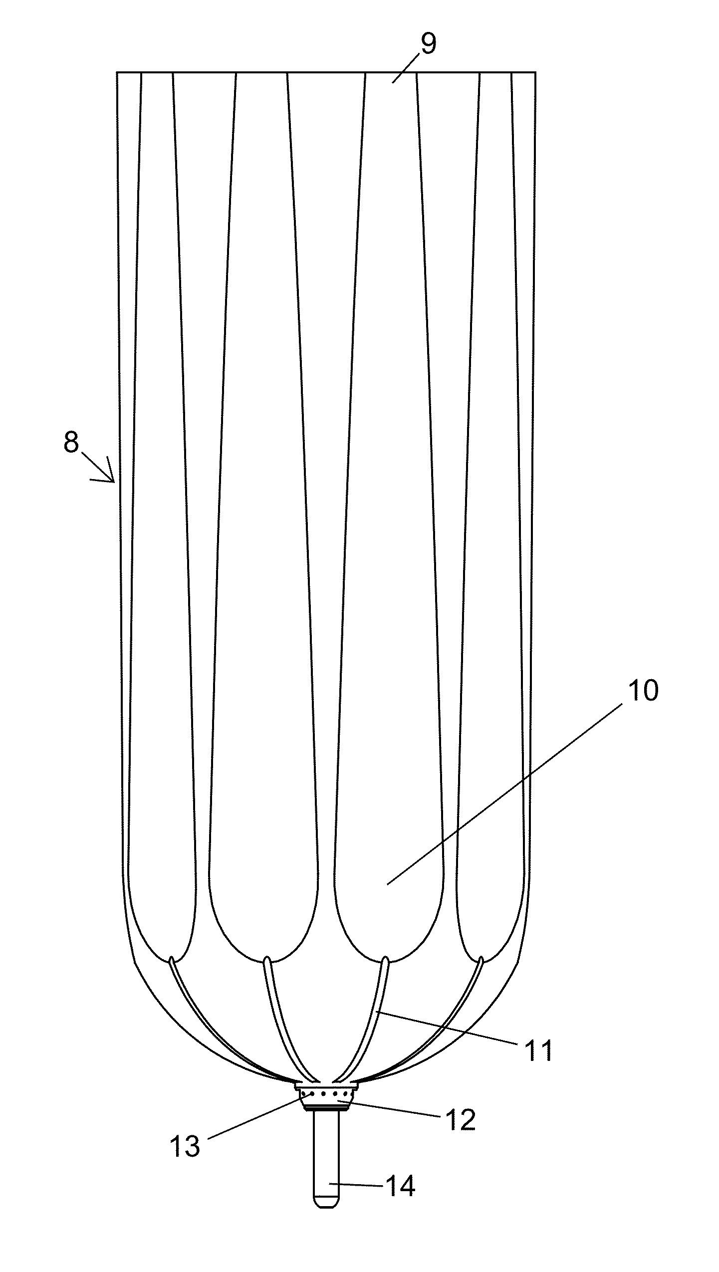
[0039]Referring initially to FIG. 1, the multi-ply surface area multiplying textile layer 1, which comprises a five ply distal end knitted layer 4, three ply knitted layer 3 and one ply knitted layer 2, a laminate transition area 5, a raised annular ring 6, and an airflow seal 7 will now be described. For example, the five ply layer 4 and the three ply layer 3 are on...


PUM


Abstract

The negative gauge pressure dynamic convection system for artificial limb system is to be attached to a residual limb of an amputee. The device provides thermal energy transfer from within an artificial limb to the ambient atmosphere through regulated cyclical differential pressure airflow into the sealed environment between both the residuum and the inside of the suspension liner of an artificial limb and as an alternate embodiment between the rigid socket and the outside of the suspension liner or a combination of both. The system may include a multi-ply surface area multiplying textile layer; a limb-conformable convection suspension liner; an artificial limb socket with an over-molded enclosure for system components; a convection manifold assembly; a convection control system, which includes a continuously operating airflow generation device, and a rising edge triggered negative gauge pressure regulation device, such as an electromechanical binary airflow proportioning device, or an alternate mechanical binary airflow proportioning device.

Description

RELATED APPLICATIONS[0001]This application claims the benefit U.S. Provisional Application Nos. 61 / 840,404 filed Jun. 27, 2013, 61 / 911486 filed Dec. 4, 2013, all of which are hereby incorporated herein in their entireties by reference.FIELD OF THE INVENTION[0002]The present invention relates to the field of artificial limbs, and, more particularly, liners employed in artificial limbs, related systems and related methods.BACKGROUND OF THE INVENTION[0003]Tests measuring the thermal conductivity of 23 different commercially available prosthetic liners and common socket materials by Klute, G. K., et al. (2007), in a paper titled “The thermal conductivity of prosthetic sockets and liners” Prosthet Orthot Int., 31(3): p. 292-9 found that all samples tested effectively trapped thermal energy. Hachisuka et al. (2001) in an article titled “Moisture permeability of the total surface bearing prosthetic socket with a silicone liner: is it superior to the patella-tendon bearing prosthetic socket...

Claims


Application Information

Patent Timeline
Patent Type & Authority Patents(United States)
IPC IPC(8): A61F2/80A61F2/68A61F2/78A61F2/76A61F2/60A61F2/50A61F2/70A61F2/74
CPCA61F2/80A61F2/68A61F2/7812A61F2/602A61F2/70A61F2002/501A61F2002/5032A61F2002/5035A61F2002/741A61F2002/742A61F2002/747A61F2002/7655A61F2002/7665A61F2002/7818A61F2002/7875A61F2002/802A61F2002/805A61F2/74A61F2/741A61F2/742A61F2002/5007A61F2002/5083A61F2002/607A61F2002/807
Inventor KING, CHARLES RUSSELL
Owner KING CHARLES RUSSELL
Why Eureka
Try Eureka