Portable fluid delivery system for the nasal and paranasal sinus cavities

a technology fluid delivery systems, which is applied in the field of portable fluid delivery systems for nasal and paranasal sinus cavities to achieve the effects of convenient portability, quick and simple handheld use, and convenient carrying

Active Publication Date: 2016-08-02
MONAGHAN MEDICAL
View PDF59 Cites 4 Cited by
  • Summary
  • Abstract
  • Description
  • Claims
  • Application Information

AI Technical Summary

Benefits of technology

[0005]The components of an irrigator comprise a size and weight that simply do not allow for convenient transport, portability or even quick and simple handheld usage. There is a need for an irrigator device that will easily fit in well with a person's daily needs or activities such that the person need not have to change his or her daily routines or schedule times of day to be close to an irrigator or an outlet for the irrigator. The device should be easy to carry on one's person and provide convenience to the needs of a patient. There is a need for an all-in-one irrigator device that contains all the components necessary to successfully use an irrigator, without the heavy weight of its components and without tubing connected to heavy equipment, and without compromising the performance needed to penetrate the nasal and paranasal cavities. There is also the need to eliminate the requirement to be close to a power outlet to be able to use an irrigator.
[0006]A portable, ready-to-use device for nasal irrigation and / or drug delivery of fluid is provided herein, which allows for more convenient use, not requiring connecting tubing, a power supply cord, or a heavy or bulky compressor. The irrigator device has an internal airflow regulating system within a connected pressurized air supply source with airflow regulating components that replace heavy, large components to power atomization of fluid for irrigation or drug delivery to the nasal passages without compromising effectiveness or reach of the atomized fluid. The airflow regulating system comprises an air outlet, a pump, a motor, a filter for filtering incoming air, and a circuit board to control the motor. The pump is in communication with the main canister and the motor, and the filter connects to the pump. The motor is driven by one of: a battery contained within the pressurized air supply source or an external power supply source. A canister for holding fluid attaches on top of the pressurized air supply source and an insert fits that over a fluid channel in the canister to create a venturi effect and draw the fluid out. The entire device described herein, as a whole, (meaning all its parts and components) is lightweight (i.e., less than 2 pounds) and easy to handle and hold either single-handedly or with both hands; thereby, cutting down the weight and bulky equipment otherwise necessary by more than half. Where the device is used without an external power supply, the lightweight device weighs only about one pound. With an external power supply, the portable device described herein weight about 1.5 lbs. In addition, the device is small enough to be carried or moved with ease to provide for convenience while still having the power to reach the desired areas of the nasal passage and the particle size to minimize or eliminate the risk of pulmonary delivery and keep the aerosol in the nasal cavity. The device can also be readily used at any time without having to search for a nearby electrical outlet, when a battery pack within the pressurized air supply source has sufficient charge.
[0008]As stated above, the device requires no connecting tubing and no power cord during use to power the atomization of fluid. Instead, the airflow regulating system within the pressurized air supply source comprises substantially all or all components necessary to regulate and control the air supply. The pressurized air supply source houses a motor that drives a pump, which receives filtered air through a filter on the pressurized air supply source, and an optional rechargeable battery to drive the motor. An inlet air manifold of the filter connects to the pump via a pump air inlet post to eliminate additional tubing within the pressurized air supply source. A circuit board precisely controls the motor speed to ensure the proper airflow, ensures the battery voltage is maintained at a proper voltage for operation and drives indicators to inform the user when the battery requires charging and is being charged. The AC / DC power supply charges the battery and provides the user the option to operate the device on mains power when the battery is discharged. The motor controller board may utilize pulse width modulation or alternatively digital control to control motor speed within a narrow band to regulate airflow generated by the pump.
[0009]A single membrane on one external side of the pressurized air supply source contains substantially all the electrical components externalized to the user and incorporates a single ribbon connector. A power jack is the only electrical component outside the single membrane. A tethered cover may be used to cover the power jack and reduce fluid and dust ingress to the device when the power supply is not plugged into the irrigator, such as when the pressurized air supply source houses a battery. When pressurized air is introduced through the air inlet of the canister, a venturi effect is created, drawing fluid up between the air exit port and fluid channel and expelling the fluid as a mist through a discharge port in the fluid channel. The mist may comprise medication, saline or other non-active ingredients to provide moisture.

Problems solved by technology

The components of an irrigator comprise a size and weight that simply do not allow for convenient transport, portability or even quick and simple handheld usage.

Method used


Image

  • Portable fluid delivery system for the nasal and paranasal sinus cavities
  • Portable fluid delivery system for the nasal and paranasal sinus cavities
  • Portable fluid delivery system for the nasal and paranasal sinus cavities

Examples


Embodiment Construction

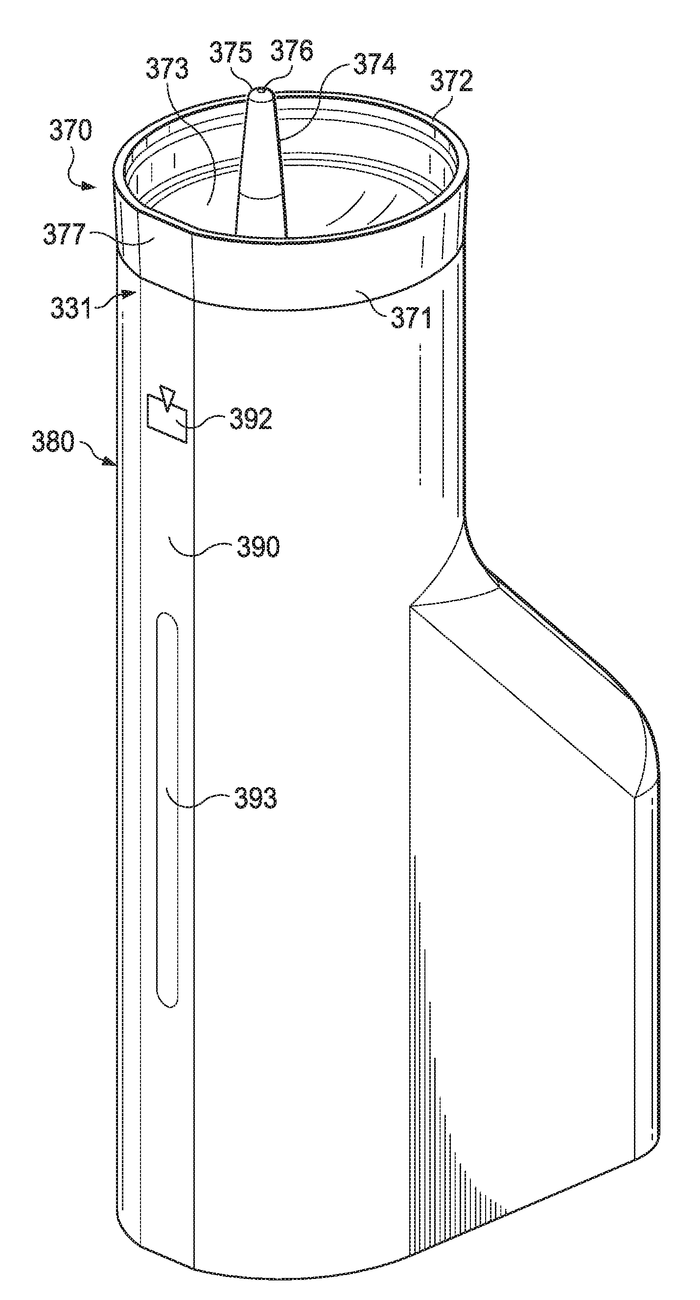
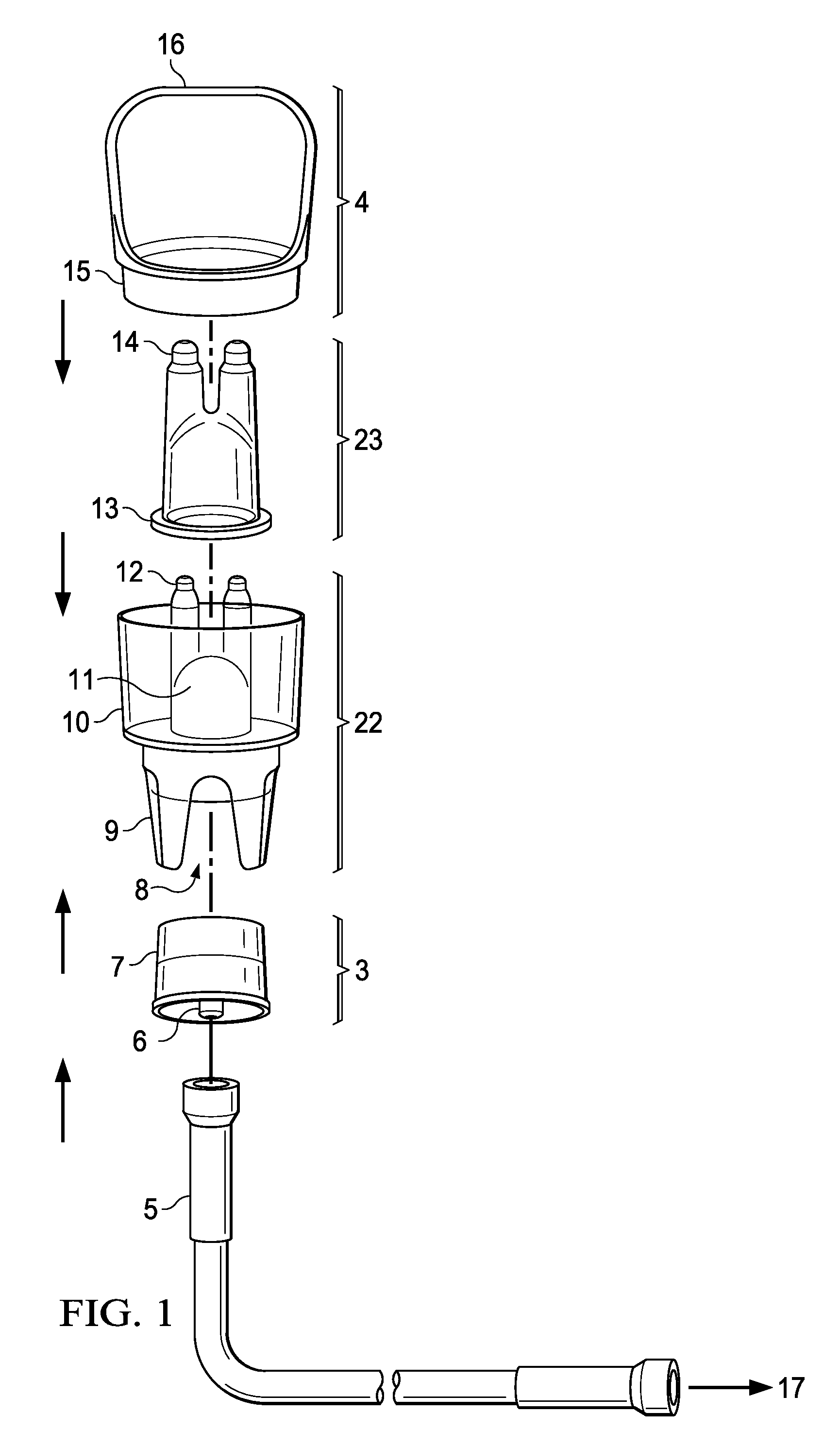
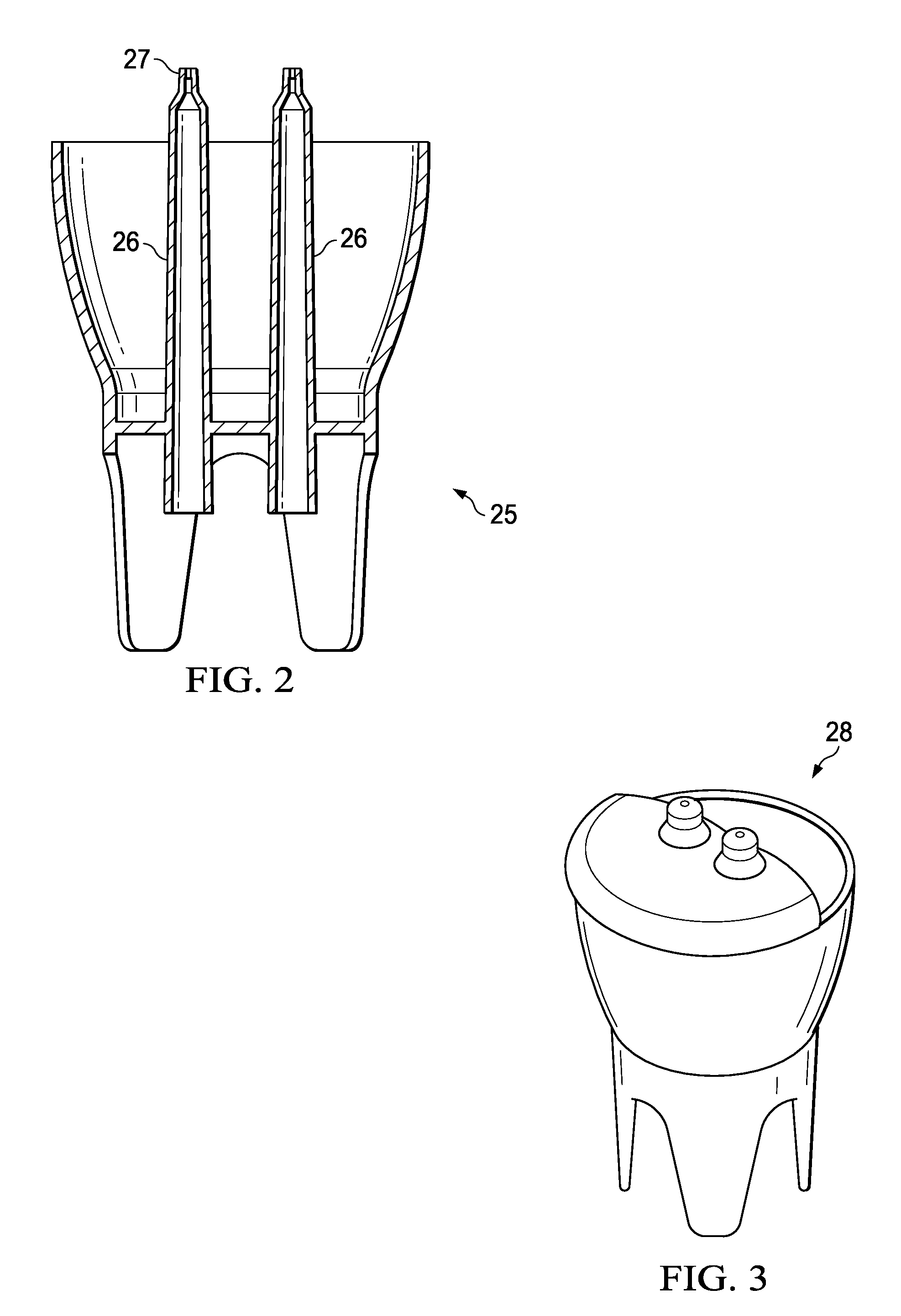
[0056]The present invention improves upon current irrigator designs and provides a method of delivering fluid to the nasal passages with little interaction required by the user, under sufficient pressure to stent-open the airway, and with particles of a size to ensure that the majority of the mist is retained or deposited within the upper airway. The invention also provides a nasal irrigator designed to deliver a mist to the upper airway through both nostrils simultaneously.

[0057]In one aspect, a nasal irrigator of the present invention comprises a main canister with a reservoir for holding fluid, wherein the canister includes at least two air exit ports; a removable insert with a circular base that fits within said main canister, wherein the insert includes at least two fluid channels that mate with said air exit ports of the main canister, said fluid channels comprising two tubes ending in a common bell housing above the base, wherein said base holds the insert just off of the mai...


PUM


Abstract

A pressurized air supply source for a portable nasal irrigator houses an airflow regulating system, instead of external bulky, heavy components, to power the atomization of fluid for irrigation of nasal passages. The airflow regulating system is made up of a pump, a motor to drive the pump, a filter with an inlet air manifold connected to the pump to eliminate additional tubing within the pressurized air supply source, and an optionally rechargeable battery to drive the motor. An external AC / DC power supply may charge the battery or operate the device when the battery is in a discharged state. A canister for holding fluid attaches on top of the pressurized air supply source and an insert fits that over a fluid channel in the canister to create a venturi effect and draw the fluid out. The pressurized air supply source creates a clinically effective airflow despite its small size.

Description

CROSS-REFERENCE TO RELATED APPLICATIONS[0001]This application is a continuation-in-part of and claims filing priority rights with respect to currently pending U.S. patent application Ser. No. 13 / 414,439 filed Mar. 7, 2012, which was published Jun. 28, 2012, as U.S. Publication 2012 / 0160237; and Ser. No. 13 / 404,623 filed Feb. 24, 2012, which was published Jun. 21, 2012, as U.S. Publication 2012 / 0152238; and Ser. No. 12 / 829,198 filed Jul. 1, 2010, which was published Jan. 5, 2012, as U.S. Publication 2012 / 0000460. The technical disclosures of all of the above-mentioned applications are hereby incorporated herein by reference.TECHNICAL FIELD[0002]The present invention generally relates to devices used for administering fluid to the upper airway in mist or droplet form, either for the irrigation of the nasal passages or the delivery of medication.BACKGROUND OF THE INVENTION[0003]Devices used for administering liquid medication to a patient by way of mist or liquid droplets are generally...

Claims


Application Information

Patent Timeline
Patent Type & Authority Patents(United States)
IPC IPC(8): A61M11/02A61M11/06A61M15/08A61M3/02A61M16/00
CPCA61M11/06A61M3/025A61M3/0279A61M15/08A61M2205/583A61M2205/75A61M16/0063A61M2205/8206A61M2210/0618A61M16/107
Inventor FLICKINGER, WILLIAM J.
Owner MONAGHAN MEDICAL
Why Eureka
Try Eureka