
Path tracking for directional drilling as applied to attitude hold and trajectory following

a directional drilling and path tracking technology, applied in the direction of directional drilling, survey, borehole/well accessories, etc., can solve the problems of significant difficulties in achieving conventional technologies

Active Publication Date: 2016-08-02
SCHLUMBERGER TECH CORP
View PDF20 Cites 7 Cited by
  • Summary
  • Abstract
  • Description
  • Claims
  • Application Information

AI Technical Summary

Benefits of technology

The patent text describes a method and apparatus for directional drilling for wellbores. The technical effects of the patent include the ability to control the drilling procedure to achieve both path tracking for path following and attitude hold applications. This allows for better control of the drilling process to minimize errors and improve wellbore trajectory. The method and apparatus can be used in exploratory drilling for geotechnical features and can be installed on a computer-readable medium or directly control the drilling apparatus. The patent also includes a model that simplifies the dynamics of drilling and a series of simulations to allow for pre-drilling planning. Overall, the patent provides a solution for improving the efficiency and accuracy of directional drilling for wellbores.

Problems solved by technology

It is also the case that it is required to follow a predefined well plan as closely as possible, where the well plan has been optimally constructed off-line to minimize the measured depth of drilling given a set of target coordinates and drilling constraints, however conventional technologies have significant difficulties in achieving this result.

Method used


Image

  • Path tracking for directional drilling as applied to attitude hold and trajectory following
  • Path tracking for directional drilling as applied to attitude hold and trajectory following
  • Path tracking for directional drilling as applied to attitude hold and trajectory following

Examples


Embodiment Construction

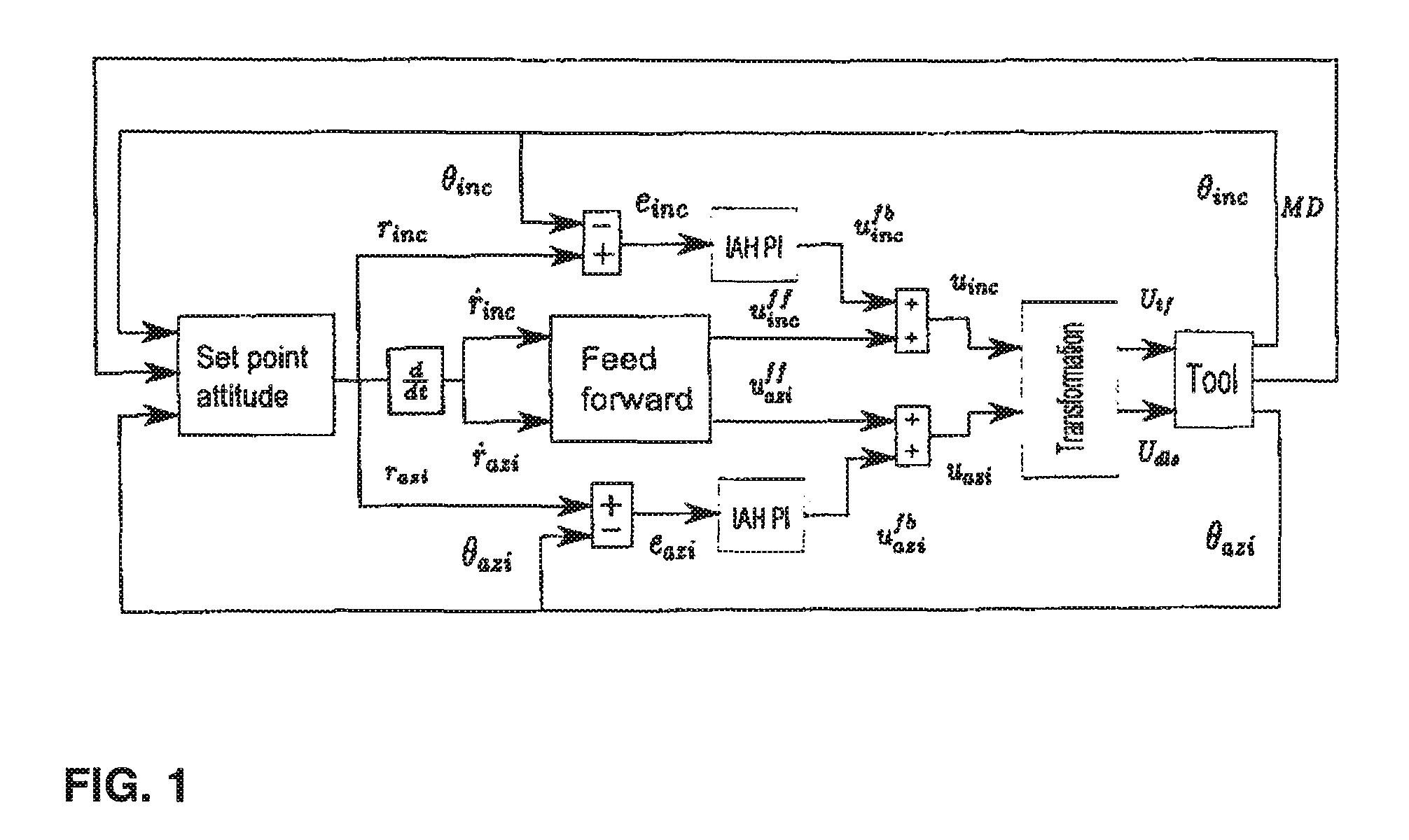
[0013]In one aspect, a driver is described to provide for drilling control for exploration of geotechnical features. In the illustrated examples that follow, the methodologies may be conducted such that they may be contained on a computer readable medium, for example, or may be installed in a computer readable medium such as a hard disk for control of drilling functions. In some aspects, simulations may be run to allow an operator to preview the actions to be chosen. In other aspects, direct control of the drilling apparatus may be accomplished by the methodologies and apparatus described. In one example embodiment, a model is used, derived from kinematic considerations. In this simplified model, lateral and torsional dynamics of the drill string and the bottom hole assembly, (hereinafter called “BHA”) are ignored. In this specific example embodiment provided:

[0014]θ.inc=Vrop⁡(Udls⁢cos⁢⁢Utf-Vdr)Equation⁢⁢1θ.azi=Vropsin⁢⁢θinc⁢(Udls⁢sin⁢⁢Utf-Vdr)Equation⁢⁢2

where:

θinc is the inclinatio...


PUM


Abstract

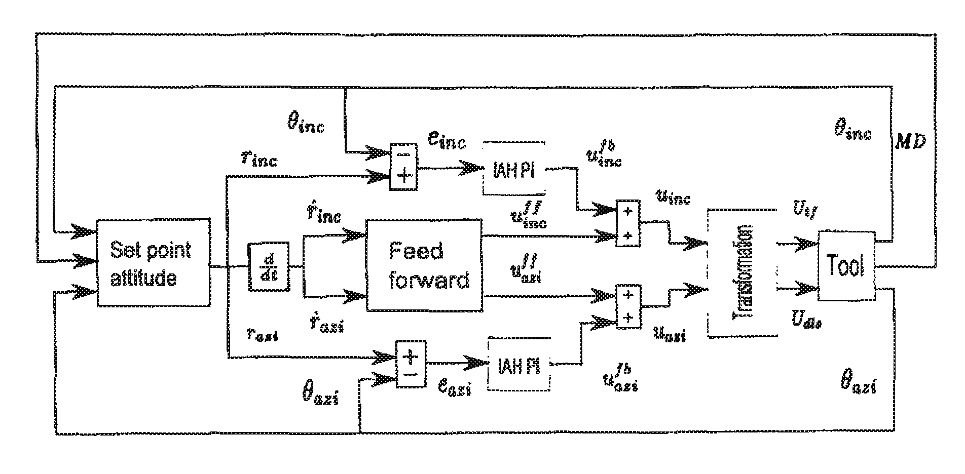
A method for directional control of a drilling system includes generating a set point attitude on an outer loop to establish a path to be followed by the drilling system. The set point attitude may be generated using a surface controller based on inclination and azimuth measurements made at the drilling system and a measured depth of the drilling system. A downhole inclination and azimuth hold system is used on an inner loop to control drilling along the path established by the set point attitude. The inclination and azimuth hold system processes the set point attitude to compute a toolface control input and a dogleg severity control input which are applied to the drilling system to control the drilling system to drill along the established path.

Description

FIELD OF THE INVENTION[0001]Aspects relate to directional drilling for wellbores. More specifically, aspects relate to directional drilling where control of the drilling procedure is used to develop path tracking for both path following and attitude hold applications.BACKGROUND INFORMATION[0002]Directional drilling is an important aspect of discovery of petroleum products in geotechnical formations. Directional drilling naturally gives rise to the requirement to autonomously control the attitude and trajectory of wells being drilled. Drivers may be used to control the drilling in order to maximize economic return of the drilling. Practical drivers for this include drivers that reduce well tortuosity due to target attitude overshoot as well as well collision avoidance. Conventional systems have proposed applications that enable sliding mode control to minimize errors in position and attitude. Other conventional technologies have approached path planning and trajectory following as an...

Claims


Application Information

Patent Timeline
Patent Type & Authority Patents(United States)
IPC IPC(8): E21B44/02E21B7/10E21B47/022E21B44/00E21B7/04
CPCE21B44/005E21B47/022E21B7/10E21B7/04E21B44/02
Inventor BAYLISS, MARTIN THOMAS
Owner SCHLUMBERGER TECH CORP
Learn More