Instruction beam detection apparatus and method of detecting instruction beam
a detection apparatus and instruction beam technology, applied in the direction of television systems, electric programme control, program control, etc., can solve the problems of difficult selective detection of instruction beams, shortening the life of internal batteries of remote control devices, and difficulty for operators to recognize operation buttons necessary for transmitting commands. , to achieve the effect of improving the detection accuracy of instruction beams, and reducing the influence of environmental ligh
- Summary
- Abstract
- Description
- Claims
- Application Information
AI Technical Summary
Benefits of technology
Problems solved by technology
Method used
Image

Examples
first embodiment
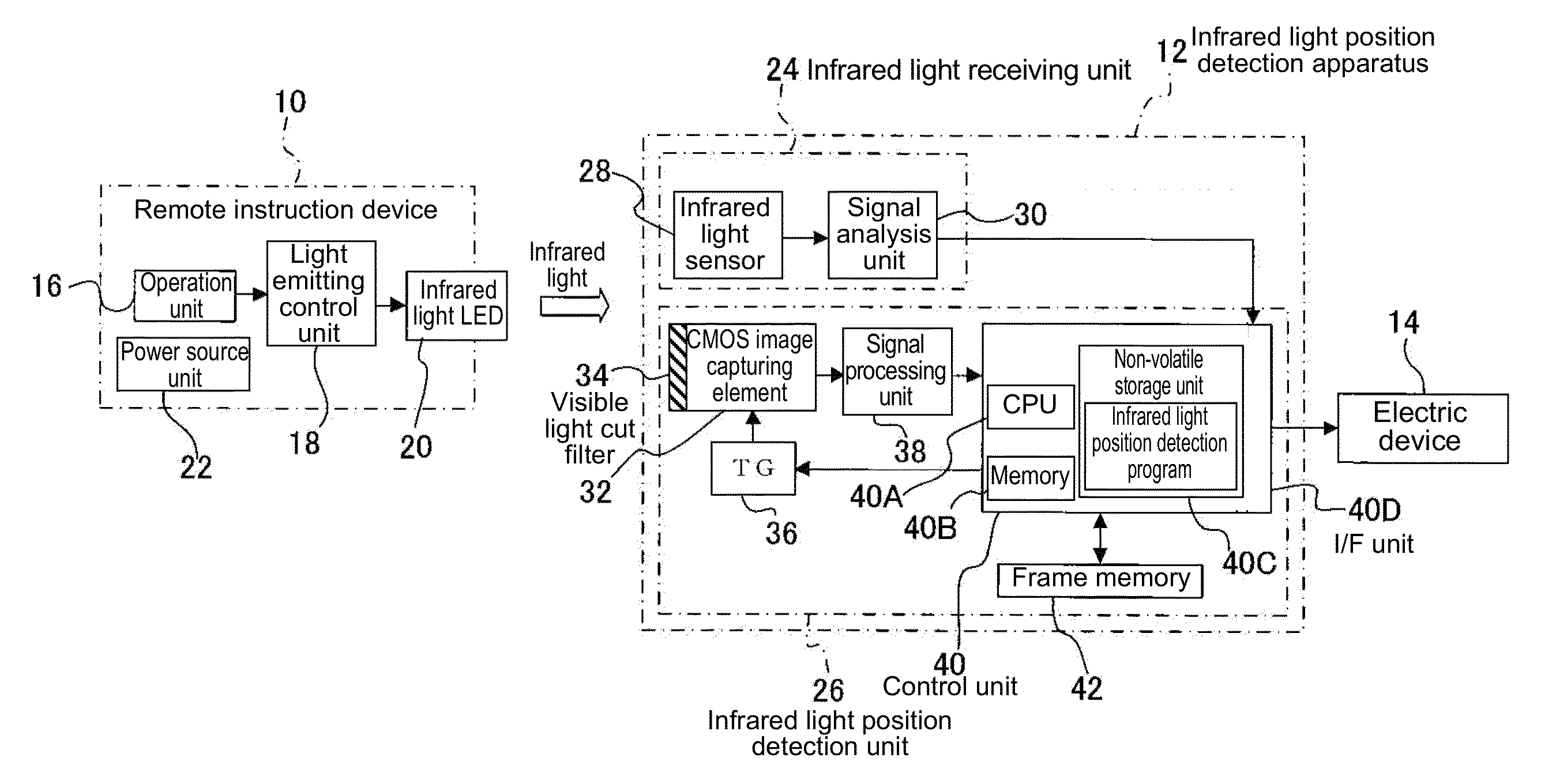
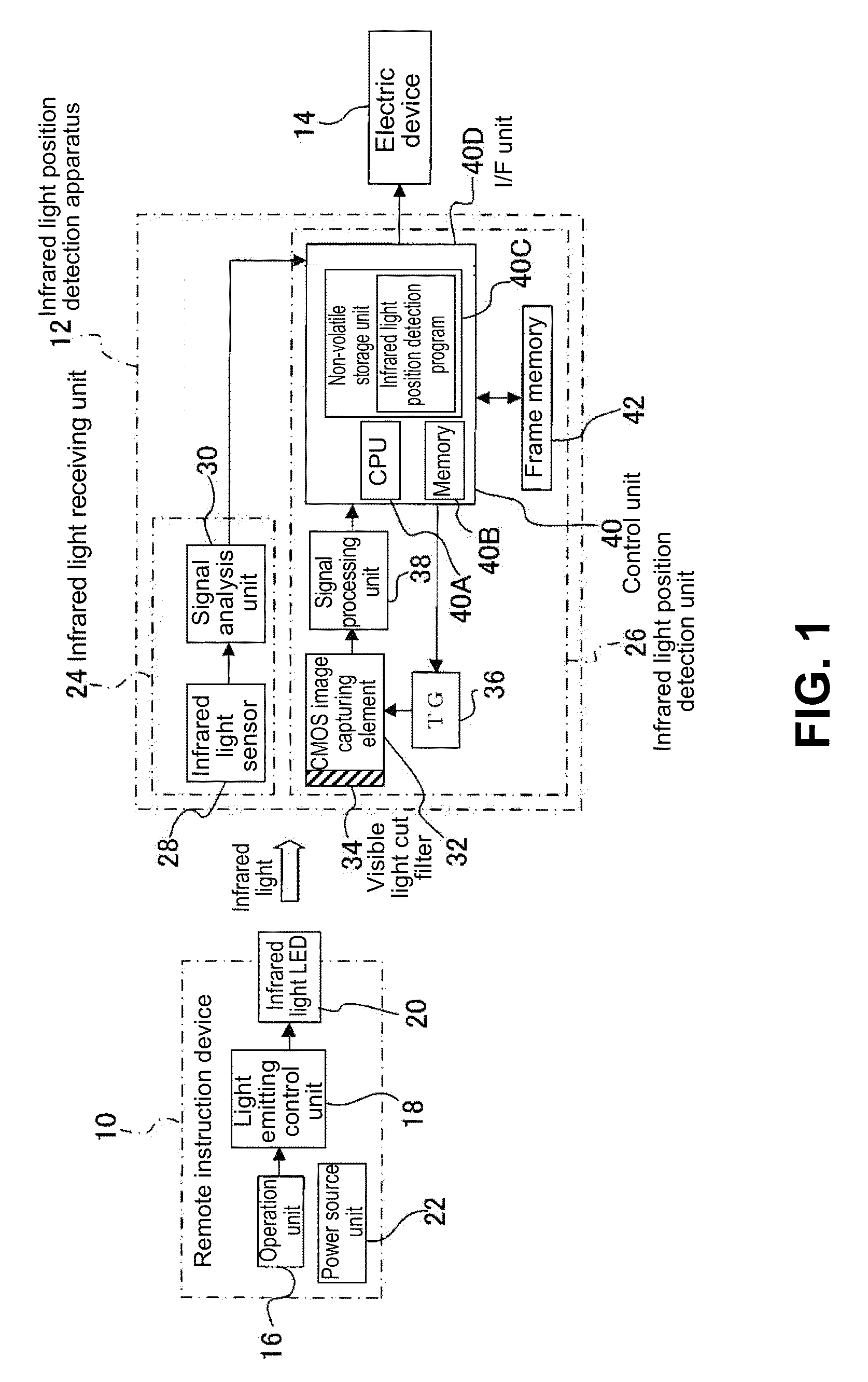
[0066]A first embodiment of the present invention will be explained. FIG. 1 is a block diagram showing a configuration of an infrared light position detection apparatus 12 and a remote instruction device 10 in addition to an electric device 14 to be an object of remote control according to the first embodiment of the present invention. It is noted that the electric device 14 may include various electric devices such as a television set, an audio visual (AV) device, a personal computer (PC), an air conditioner, and the like.
[0067]In the embodiment, the remote instruction device 10 is configured to be an instruction device, or so-called a remote control device, to be operated by a user holding the remote instruction device 10 to remotely control the electric device 14. As shown in FIG. 1, the remote instruction device 10 includes an operation unit 16, a light emitting control unit 18, an infrared light LED (Light Emitting Diode) 20, and a power source unit 22.
[0068]In the embodiment, ...
second embodiment
[0104]A second embodiment of the present invention will be explained next. It should be noted that the infrared light position detection apparatus 12 in the second embodiment has a configuration similar to that of the infrared light position detection apparatus 12 in the first embodiment. Accordingly, components in the second embodiment similar to those in the first embodiment are designated with the same reference numerals, and explanations thereof are omitted.
[0105]An infrared light position detection process according to the second embodiment will be explained next with reference to FIG. 5. FIG. 5 is a flow chart showing an operation of the infrared light position detection apparatus 12 in the infrared light position detection process according to the second embodiment of the present invention.
[0106]It should be noted that only a difference from the infrared light position detection process in the first embodiment shown in FIG. 3 will be explained. It also should be noted that th...
third embodiment
[0132]A third embodiment of the present invention will be explained next. It should be noted that components in the third embodiment similar to those in the first embodiment and the second embodiment are designated with the same reference numerals, and explanations thereof are omitted.
[0133]FIG. 7 is a block diagram showing a configuration of an infrared light position detection apparatus 13, the remote control device 10 and the electric device 14 according to the third embodiment of the present invention.
[0134]As shown in FIG. 7, different from the infrared light position detection apparatus 12 in the first embodiment, the infrared light position detection apparatus 13 in the third embodiment includes a near infrared light transmission band pass filter 44 instead of the visible light cut filter 34. Further, in the infrared light position detection apparatus 13, the frame memory 42 is omitted. A global shutter is disposed on the CMOS image capturing element 32, so that it is possibl...
PUM
 Abstract
Description
Claims
Application Information
 - R&D
- Intellectual Property
- Life Sciences
- Materials
- Tech Scout
- Unparalleled Data Quality
- Higher Quality Content
- 60% Fewer Hallucinations
Browse by: Latest US Patents, China's latest patents, Technical Efficacy Thesaurus, Application Domain, Technology Topic, Popular Technical Reports.
© 2025 PatSnap. All rights reserved.Legal|Privacy policy|Modern Slavery Act Transparency Statement|Sitemap|About US| Contact US: help@patsnap.com