Flight instrument displaying a variable rotational speed of a main rotor of an aircraft

a technology of flight instruments and rotating rotors, which is applied in the direction of aircrafts, rotors, aircraft components, etc., can solve the problems of engine flameout, mechanical, physical and aerodynamic limitations, and damage to mechanical power-transmission,

Active Publication Date: 2016-08-09
EUROCOPTER
View PDF14 Cites 5 Cited by
  • Summary
  • Abstract
  • Description
  • Claims
  • Application Information

AI Technical Summary

Benefits of technology

[0033]Thus, the purpose of the present invention is to propose a flight instrument and a procedure that make it possible to meet the needs of the pilots of rotary-wing aircraft in terms of managing the variable setpoint for the rotational speed of the main rotor.
[0034]One goal of the present invention relates to a flight instrument that makes it possible to determine flight information and to ensure the visual conveyance of this information to the pilots of rotary-wing aircraft. More specifically, one of the goals of the present invention involves the task of displaying information about the rotational speed of the main rotor of a rotary-wing aircraft.

Problems solved by technology

In fact, numerous mechanical, physical, and aerodynamic limitations must be taken into consideration by the pilot while the aircraft is being flown.
In fact, if these fixed limits are exceeded, damaging effects on the mechanical power-transmission train may occur, or a risk of engine flameout may arise, for example, due to excessively sudden deceleration.
An analog instrument may still be present; however, in such a case it constitutes a back-up instrument in the event of a failure of the digital display.
Furthermore, the instrument that currently indicates this rotational speed of the main rotor does not provide effective assistance to the pilot, because the variable setpoint does not appear on this instrument.
However, because the setpoint can vary continuously, such an instrument would make heavy demands on the attention of the pilot of the aircraft in order to identify the variable setpoint for the current rotational speed of the main rotor.
Similarly, even if the pilot continues to monitor the rotational speed of the main rotor by ear, the pilot can no longer maintain accurate and effective sound-based control of this rotational speed of the main rotor (that is, control based on the frequency of the sound emitted by the rotor).
Furthermore, the use and the broader dissemination, in the near future, of such a variable setpoint may be confusing or disconcerting to pilots of rotary-wing aircraft, because it calls into question certain customary practices for flying such an aircraft in relation to its traditional use.
Conversely, the use of inappropriate instruments may limit the range covered by the rotational speed of the main rotor and / or its dynamic operation, thereby limiting the improvements contributed by the use of this variable setpoint in terms of the operation of the aircraft per se.

Method used


Image

  • Flight instrument displaying a variable rotational speed of a main rotor of an aircraft
  • Flight instrument displaying a variable rotational speed of a main rotor of an aircraft
  • Flight instrument displaying a variable rotational speed of a main rotor of an aircraft

Examples


Embodiment Construction

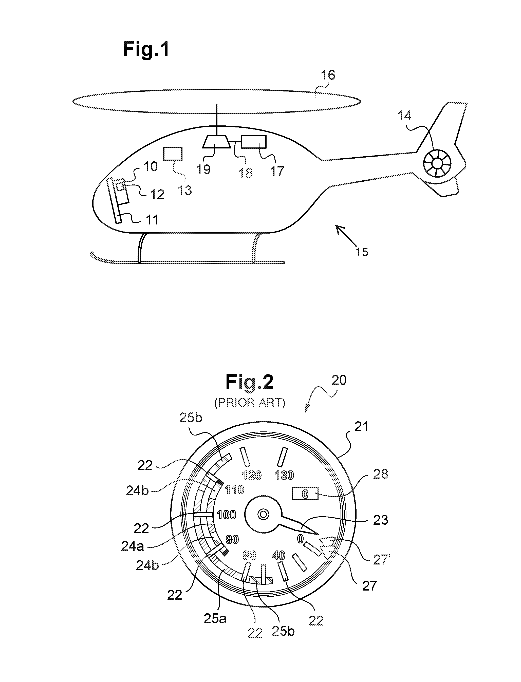
[0103]According to FIG. 1, a rotary-wing aircraft 15 includes a main rotor 16, a rear rotor 14, a turboshaft engine 17, and a main power transmission gearbox 19. The turboshaft engine 17 includes a free turbine 18 that rotatively drives the main rotor 16, as well as the rear rotor 14, doing so by means of the main power transmission gearbox 19. Furthermore, the aircraft 15 includes means 13 for determining atmospheric parameters and the flight parameters of the aircraft 15 that are useful in terms of the operation and piloting of this aircraft 15.

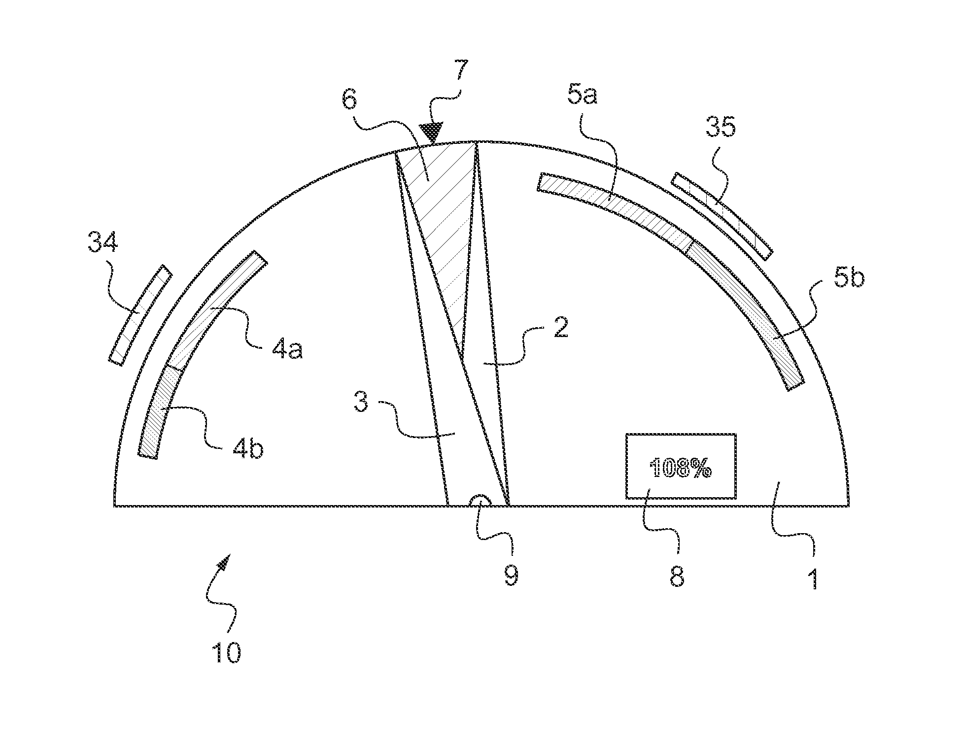
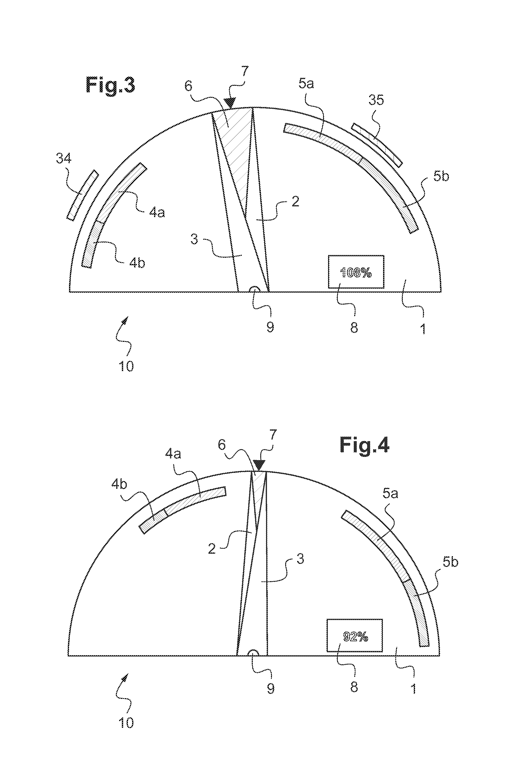
[0104]The aircraft 15 also includes an instrument panel 11 equipped with various instruments, including a flight instrument 10 that displays first pieces of information about the rotational speed of the main rotor 16 and second pieces of information about the rotational speed of the free turbine 18 of the turboshaft engine 17. This flight instrument 10 also includes computation means 12, and is shown in FIGS. 3 and 4.

[0105]FIG. 2 shows a fl...


PUM


Abstract

A flight instrument that displays the rotational speed of a main rotor of a rotary-wing aircraft, with the flight instrument including display means, a first indicator of a setpoint for the rotational speed of the main rotor, a second indicator of the first current value of the rotational speed of the main rotor, and third and fourth indicators of the limit values of the rotational speed. The setpoint for the rotational speed of the main rotor is variable and the first indicator is stationary on the display means, with the second, third and fourth indicators being movable in relation to the first indicator.

Description

BACKGROUND OF THE INVENTION[0001](1) Field of the Invention[0002]The present invention lies in the area of aircraft flight instruments. More specifically, the invention relates to a flight instrument that displays a variable rotational speed of a main rotor of a rotary-wing aircraft, and also relates to a flight instrument procedure for displaying such a speed.[0003](2) Description of Related Art[0004]A rotary-wing aircraft usually includes at least one main rotor that is rotatively driven by a power plant on board the aircraft. Thus, the main rotor supports the aircraft and provides its propulsion. Such an aircraft may also include an anti-torque rear rotor, or, for example, one or two propellers.[0005]In particular, such a rotary-wing aircraft is piloted through the monitoring of numerous instruments that represent the operation of the power plant and of the aircraft. In fact, numerous mechanical, physical, and aerodynamic limitations must be taken into consideration by the pilot ...

Claims


Application Information

Patent Timeline
Patent Type & Authority Patents(United States)
IPC IPC(8): B64D45/00B64C27/57B64D43/00
CPCB64D45/00B64C27/57B64D43/00B64C27/04
Inventor VALLART, JEAN-BAPTISTEHELLIO, PATRICKGAUTHIER, PATRICIATAHERI, SETAREH
Owner EUROCOPTER
Why Eureka
Try Eureka