Imaging lens system, image capturing device and electronic device

a technology of image capturing device and lens system, which is applied in the field of imaging lens system and image capturing device, can solve the problems of low portability of the optical system, poor aberration and chromatic aberration, etc., and achieves favorable aberration correction, effective control of the total track length, and enhancement of the convergent performance of the light beam

Active Publication Date: 2016-08-09
LARGAN PRECISION
View PDF23 Cites 8 Cited by
  • Summary
  • Abstract
  • Description
  • Claims
  • Application Information

AI Technical Summary

Benefits of technology

[0013]In any of the aforementioned imaging lens systems of the present disclosure, the first lens element is configured to have positive refractive power so as to enhance the convergent performance of the light beam and to effectively control the total track length of the imaging lens system, and the second lens element has negative refractive power so as to favorably correct the aberration created by the first lens element and the chromatic aberration at the same time. Moreover, the arrangement of the first lens element with positive refractive power and the second lens element with negative refractive power is favorable for forming a telephoto structure so that certain area has a higher resolution.
[0014]When (T23+T34) / (CT3+CT4+CT5) satisfies the above condition, the adjustment of the spacings between lens elements in the middle of the imaging lens system and the thickness(es) of the lens element(s) close to the image-side end provides a sufficient space for the light beam and thereby to correct the aberration created due to constricted space.
[0015]When SD / TD satisfies the above condition, the total track length of the imaging lens system can be effectively reduced to prevent the imaging lens system from being too bulky while the incident angle of the light is controlled.
[0016]When (|f / f4|+|f / f5|) / (|f / f1|+|f / f2|) satisfies the above condition, the imaging lens system's control capability at the region close to the object-side end can be reinforced, and the lens element at the image-side end has an enhanced performance in correcting high order aberrations.
[0017]When (CT2+CT4) / (CT2−CT4) satisfies the above condition, the effective optical path length of the second lens element can be enhanced, and it is favorable for mitigating the distribution of the refractive power of the fourth lens element to correct the aberration at the periphery of the imaging lens system, thereby obtaining a better image quality of a distant view image.
[0018]When CT4 / CT3 satisfies the above condition, the thicknesses of the lens elements can be effectively controlled to improve the manufacturability of the product and reduce the sensitivity.

Problems solved by technology

Such a configuration not only results in a bulky optical system with low portability, but the arrangement of refractive power causes problems such as poor convergent performance of the light beam, aberrations and chromatic aberrations.
Moreover, the improper configuration of the spacing between and thicknesses of the lens elements may lead to the problem of insufficient space for the light beam to travel therebetween, thereby causing aberrations and high order aberrations.

Method used


Image

  • Imaging lens system, image capturing device and electronic device
  • Imaging lens system, image capturing device and electronic device
  • Imaging lens system, image capturing device and electronic device

Examples


1st embodiment

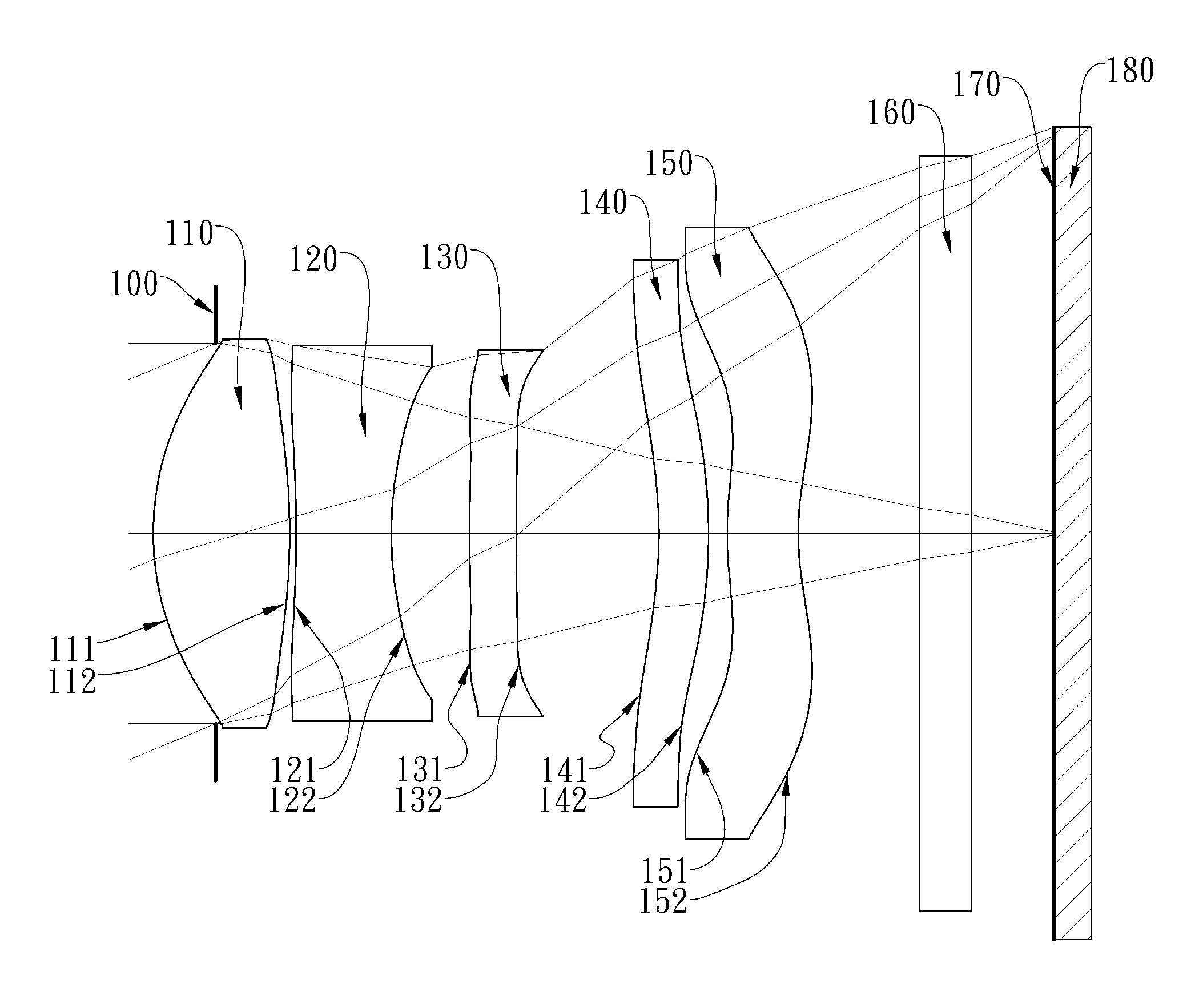
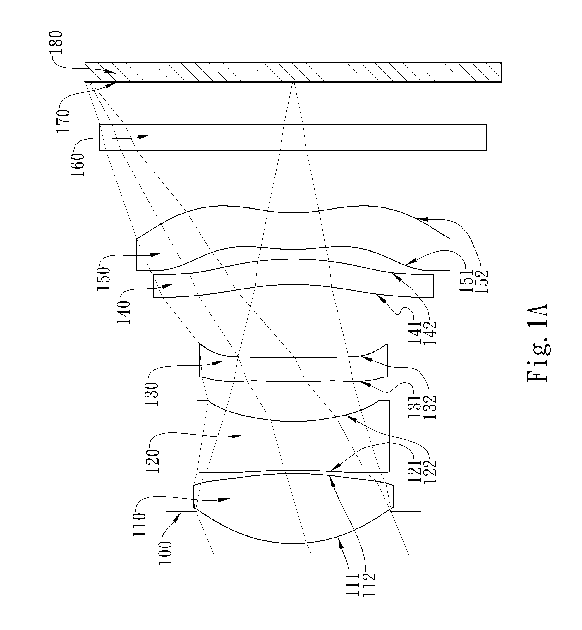
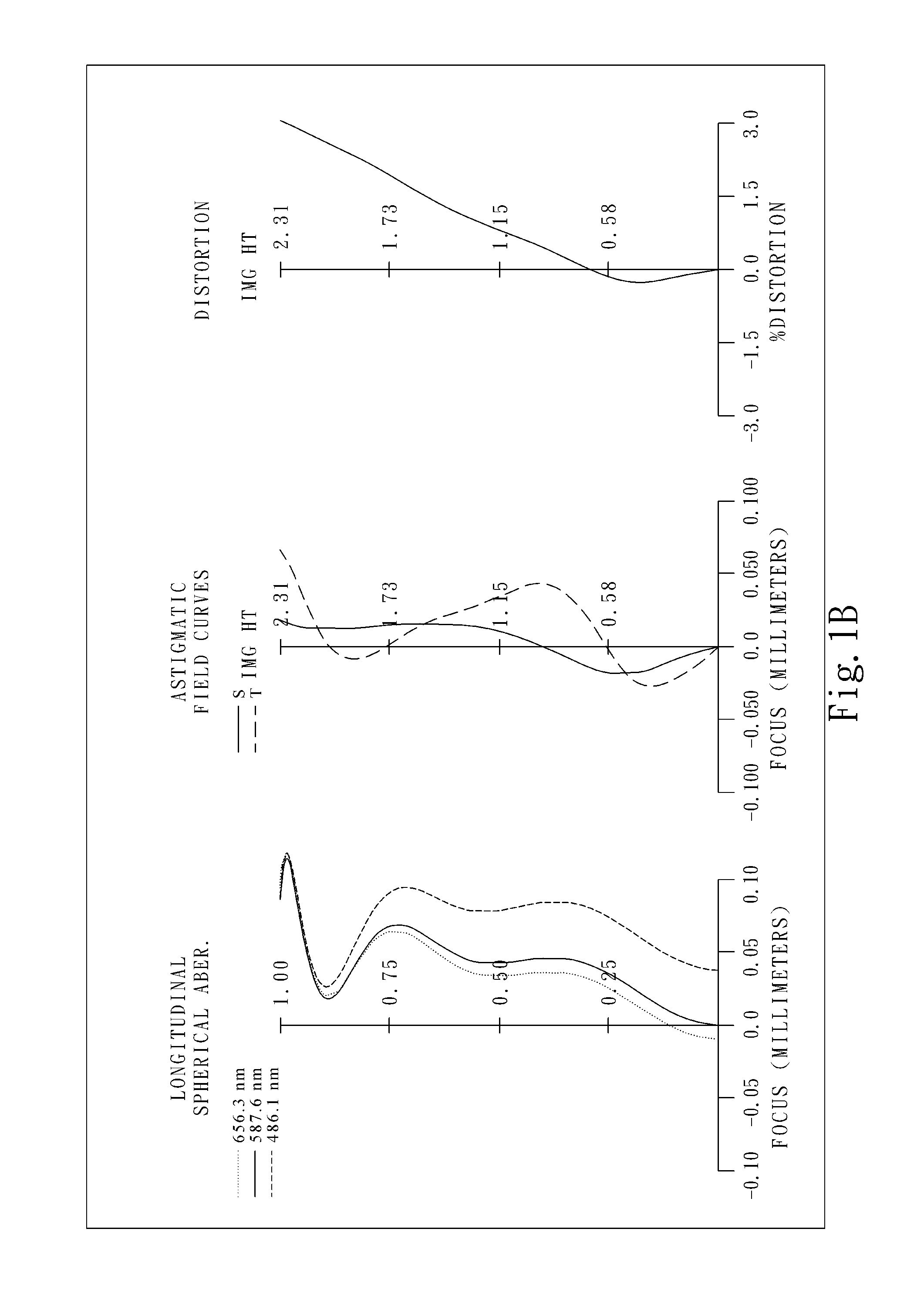
[0074]FIG. 1A is a schematic view of an image capturing device according to the 1st embodiment of the present disclosure. FIG. 1B shows, in order from left to right, longitudinal spherical aberration curves, astigmatic field curves and a distortion curve of the image capturing device according to the 1st embodiment.

[0075]In FIG. 1A, the image capturing device includes an imaging lens system (not otherwise herein labeled) of the present disclosure and an image sensor 180. The imaging lens system includes, in order from an object side to an image side, a first lens element 110, a second lens element 120, a third lens element 130, a fourth lens element 140, and a fifth lens element 150, wherein the imaging lens system has a total of five lens elements (110-150) with refractive power.

[0076]The first lens element 110 with positive refractive power has an object-side surface 111 being convex in a paraxial region thereof and an image-side surface 112 being convex in a paraxial region there...

2nd embodiment

[0107]FIG. 2A is a schematic view of an image capturing device according to the 2nd embodiment of the present disclosure. FIG. 2B shows, in order from left to right, longitudinal spherical aberration curves, astigmatic field curves and a distortion curve of the image capturing device according to the 2nd embodiment.

[0108]In FIG. 2A, the image capturing device includes an imaging lens system (not otherwise herein labeled) of the present disclosure and an image sensor 280. The imaging lens system includes, in order from an object side to an image side, a first lens element 210, a second lens element 220, a third lens element 230, a fourth lens element 240, and a fifth lens element 250, wherein the imaging lens system has a total of five lens elements (210-250) with refractive power.

[0109]The first lens element 210 with positive refractive power has an object-side surface 211 being convex in a paraxial region thereof and an image-side surface 212 being concave in a paraxial region ther...

3rd embodiment

[0121]FIG. 3A is a schematic view of an image capturing device according to the 3rd embodiment of the present disclosure. FIG. 3B shows, in order from left to right, longitudinal spherical aberration curves, astigmatic field curves and a distortion curve of the image capturing device according to the 3rd embodiment.

[0122]In FIG. 3A, the image capturing device includes an imaging lens system (not otherwise herein labeled) of the present disclosure and an image sensor 380. The imaging lens system includes, in order from an object side to an image side, a first lens element 310, a second lens element 320, a third lens element 330, a fourth lens element 340, and a fifth lens element 350, wherein the imaging lens system has a total of five lens elements (310-350) with refractive power.

[0123]The first lens element 310 with positive refractive power has an object-side surface 311 being convex in a paraxial region thereof and an image-side surface 312 being concave in a paraxial region ther...


PUM


Abstract

This disclosure provides an imaging lens system, including, in order from an object side to an image side: a first lens element with positive refractive power having a convex object-side surface; a second lens element with negative refractive power; a third lens element with refractive power; a fourth lens element with refractive power having an object-side surface and an image-side surface thereof being aspheric; a fifth lens element with refractive power having a convex object-side surface, the object-side surface and an image-side surface thereof being aspheric, and at least one of the object-side surface and the image-side surface being provided with at least one inflection point. The imaging lens system is further provided with a stop, and no lens element with refractive power is disposed between the stop and first lens element.

Description

RELATED APPLICATIONS[0001]This application claims priority to Taiwan Application Serial Number 104103389, filed Feb. 2, 2015, which is incorporated by reference herein in its entirety.BACKGROUND[0002]1. Technical Field[0003]The present disclosure relates to an imaging lens system and an image capturing device, and more particularly, to an imaging lens system and an image capturing device applicable to electronic devices.[0004]2. Description of Related Art[0005]As personal electronic products have been becoming more and more compact, the internal components of the electronic products are also required to be smaller in size than before, resulting in an increasing demand for compact imaging lens systems. In addition to the demand of miniaturization, the reduction of the pixel size of sensors in the advancement of semiconductor manufacturing technologies has enabled imaging lens systems to evolve toward the field of higher megapixels. Meanwhile, the popularity of smart phones and tablet...

Claims


Application Information

Patent Timeline
Patent Type & Authority Patents(United States)
IPC IPC(8): G02B13/18G02B9/08H04N5/232G02B13/00G02B9/60G02B3/04G02B27/00G02B5/00
CPCG02B13/0045H04N5/232G02B13/0015G02B13/18G02B27/0025G02B3/04G02B5/005G02B9/60G02B13/002
Inventor HSIEH, DUNG-YIHUANG, HSIN-HSUAN
Owner LARGAN PRECISION
Why Eureka
Try Eureka