Method and tool for automatic distribution of control code in a safety system

a technology of safety system and control code, applied in the field of methods in an industrial safety system, can solve problems such as trip effects, complex combination of system and components, and opportunities for mistakes in manual inputs and manual calculations, and achieve the effect of efficient control code distribution

Active Publication Date: 2016-08-09
ABB (SCHWEIZ) AG
View PDF14 Cites 9 Cited by
  • Summary
  • Abstract
  • Description
  • Claims
  • Application Information

AI Technical Summary

Benefits of technology

[0027]Another advantage of the invention is that the resulting complete safety system can be more fully tested earlier in the product development cycle.
[0028]The control code generated from a Cause and Effect matrix can be distributed over controllers, applications or other safety units automatically according to information from the Cause and Effect matrix and other rules or constraints. With the data from a Cause and Effect matrix or diagram, the controller-load can be calculated and thus may be applied as a constraint for the distribution. Also the cross-communication control code portions between controllers and / or applications can be automatically generated and in addition can be minimized to achieve a more efficient control code distribution.
[0029]The Cause and Effect matrix and the control code generated from it may be applied to one or more controllers in a safety system of a hazardous installation with a process from any process industry group such as: oil and gas extraction, production, refining, transport, distribution; chemical process, pharmaceutical process, process in an installation for production or processing of pulp and paper.
[0030]In another aspect of the invention, a cause and effect editor tool for manipulating a cause and effect matrix for controlling a process or equipment in an industrial safety system is disclosed, the industrial safety system comprising components with inputs and safety devices enabling signals to be generated as a result of an event or alarm, comprising a graphic user interface for creating an automated link between the event or alarm and an effect or an action to be taken upon receipt of said event or alarm signal due to the event forming a cause and effect matrix, and the industrial safety system comprising a software and / or hardware tool (CBM) for generating a control code using said cause and effect matrix, and downloading said control code to at least one safety controller, the system comprising a computer, a computer program and a graphical user interface, wherein the said cause and effect editor tool comprises a calculation device for calculating a controller load for a safety controller processing said control code based on said cause and effect matrix prior to distributing said control code to said at least one safety controller such that the calculated processing load is not exceeded in any process controller.
[0031]In another aspect of the invention, a computer program is described for carrying out the methods according to the invention. In another aspect of the invention a computer program product comprising a computer program for carrying out the method of the invention is described.
[0032]In another, further aspect of the invention, a graphical user interface is described for displaying safety data for the one or more of the apparatuses so protected; and further for providing, in response to user input at the graphical user interface, access through the graphical user interface to any of the devices and their signals or events, or actuators and their effects, actions which are ordered by the “software connections” linked in or otherwise included in the cause and effect matrix.

Problems solved by technology

This results in a complex combination of system and components.
This process takes time, it may have results that have not been predicted, and it presents opportunities for mistakes occurring in manual inputs and manual calculations.
A typical shutdown level will have a number of causes connected and will trip the effects connected to it.

Method used


Image

  • Method and tool for automatic distribution of control code in a safety system
  • Method and tool for automatic distribution of control code in a safety system
  • Method and tool for automatic distribution of control code in a safety system

Examples


Embodiment Construction

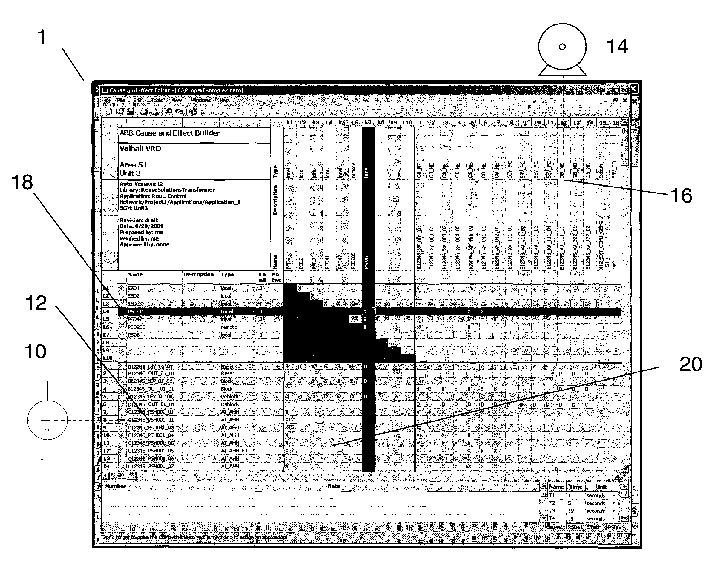
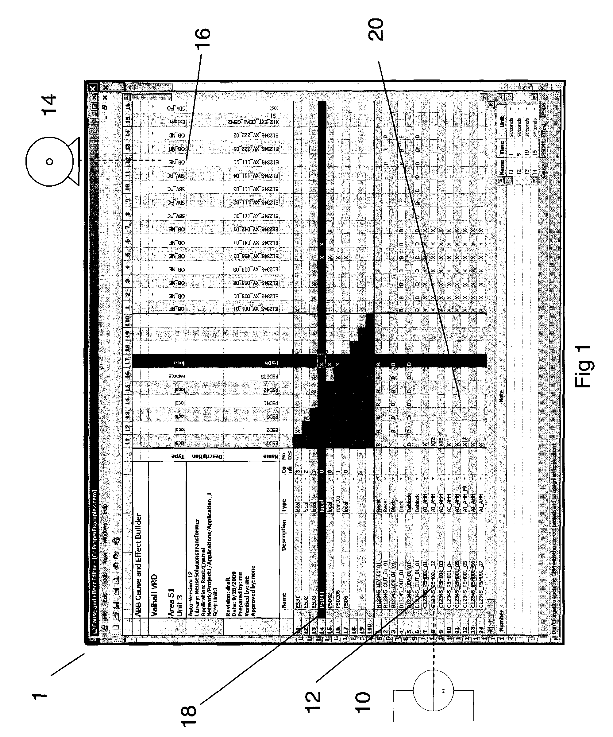
[0038]FIG. 1 shows elements of a graphical user interface of a cause and effect matrix in an industrial control system in a simplified diagram. Within an industrial control system the safety system is comprised in the control system and functions as an individual system in parallel with the control system, sometimes even enabling the same action, but with different decision chains.

[0039]A preferred embodiment of a user interface of the cause and effect editor tool comprises a cause and effect matrix (CEM). The cause and effect editor may be displayed on a suitable workstation display device and arranged with selection means for input etc. to a human machine interface (HMI). The cause and effect matrix has horizontal rows of causes and vertical columns of effects. The matrix includes a cause which is represented by a global variable and an effect which is represented by another, different global variable. Thus each cause input and each effect output are identified and represented in ...


PUM


Abstract

A method in an industrial safety system for controlling a process or equipment, which industrial safety system includes components with safety devices. The safety system enables signals to be generated as a result of an event or alarm, where the method includes creating an automated link between the event or alarm and an effect or an action to be taken upon receipt of the event or alarm signal due to the event. The method includes configuring one or more links between the event and the input, thus forming a cause and effect matrix, and also generating a control code using the cause and effect matrix for subsequent download of the control code to at least one process controller whereby a control signal is subsequently generated by at least one safety controller to initiate the action or effect.

Description

FIELD OF THE INVENTION[0001]The present invention relates to a method in an industrial safety system for controlling a process or equipment, which industrial safety system comprises components with inputs and safety devices, that enables signals to be generated as a result of an event or alarm. It includes a method and devices for handling events in an industrial system, such as alarms, enabling an action according to an event in an industrial system, such as an alarm or other events, and includes forming a Cause and Effect matrix and generating code based on that matrix.BACKGROUND OF THE INVENTION[0002]An industrial process such as an installation for extraction or production of oil and gas products has a physical implementation comprising components such as devices and apparatuses for operation, control, regulation and protection of the process. The industrial process also comprises systems for functionality, control and supervision. This results in a complex combination of system...

Claims


Application Information

Patent Timeline
Patent Type & Authority Patents(United States)
IPC IPC(8): G05B9/02G06F9/50G05B19/042G05B23/02
CPCG05B19/0421G06F9/505G05B23/027G05B2219/25229G05B2219/34355G06F2209/5019
Inventor GOHR, KATHARINA
Owner ABB (SCHWEIZ) AG
Why Eureka
Try Eureka