Optical measurement apparatus

a measurement apparatus and optical technology, applied in the field of optical measurement apparatus, can solve the problems of affecting the efficiency of the test, the inability to obtain proper test results, and the burden of work of the user, so as to prevent an erroneous test and efficiently perform the test

Active Publication Date: 2016-08-16
ARKRAY INC
View PDF27 Cites 1 Cited by
  • Summary
  • Abstract
  • Description
  • Claims
  • Application Information

AI Technical Summary

Benefits of technology

[0019]The present invention has been proposed under the circumstances described above. It is, therefore, an object of the present invention to provide an optical measurement apparatus capable of efficiently performing a test by optical measurement and preventing an erroneous test.Means for Solving the Problems

Problems solved by technology

However, in e.g. a simple measurement apparatus without a pipetting function or a small measurement apparatus in which a sample obtained from a patient is not to be stored, the test instrument Y does not automatically apply the sample to the test instrument Y. To use such a measurement apparatus, as described above, the user needs to apply the sample to the test instrument Y manually (by dipping in the case of a urine test strip or dropping using a pipette in the case of a test piece or a cuvette) and then mount the test instrument Y to the measurement apparatus.
Thus, while successively mounting test instruments to the optical measurement apparatus X, the user needs to measure the reaction completion period which differ among the test instruments, and such work is a burden on the user.
Such problems related to the reaction time and the time of application of the sample occur also in the testing of a urine test strip, a biochemical test piece and a cuvette type test instrument.
In this case, therefore, when the test instrument Y, to which the sample is applied, is accidentally left for a long time, proper test results may not be obtained when the test instrument X is mounted to the immunochromatography apparatus X.

Method used


Image

  • Optical measurement apparatus
  • Optical measurement apparatus
  • Optical measurement apparatus

Examples


Embodiment Construction

[0043]Preferred embodiments of the present invention will be described below with reference to the accompanying drawings, using an immunochromatography test instrument as an example.

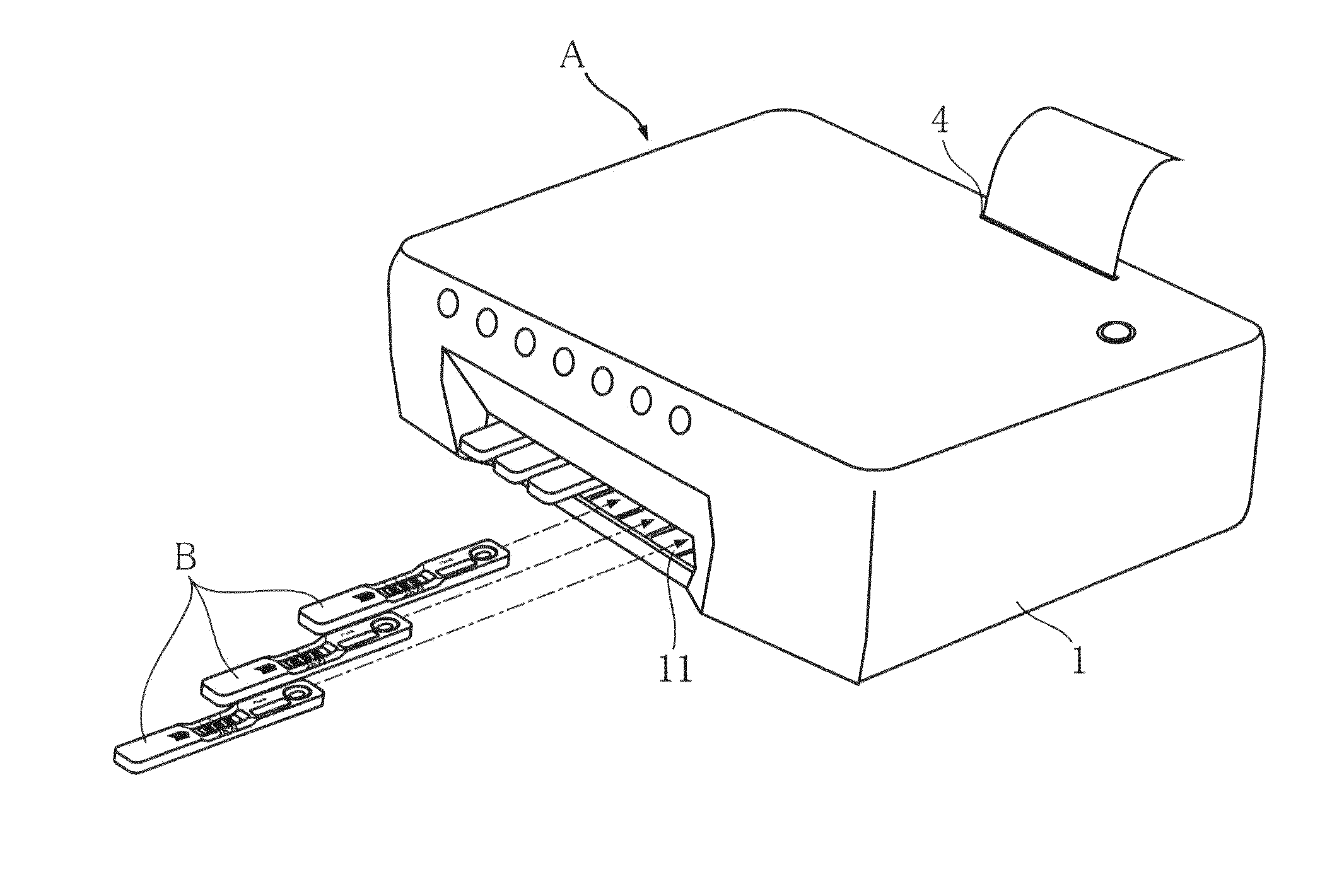
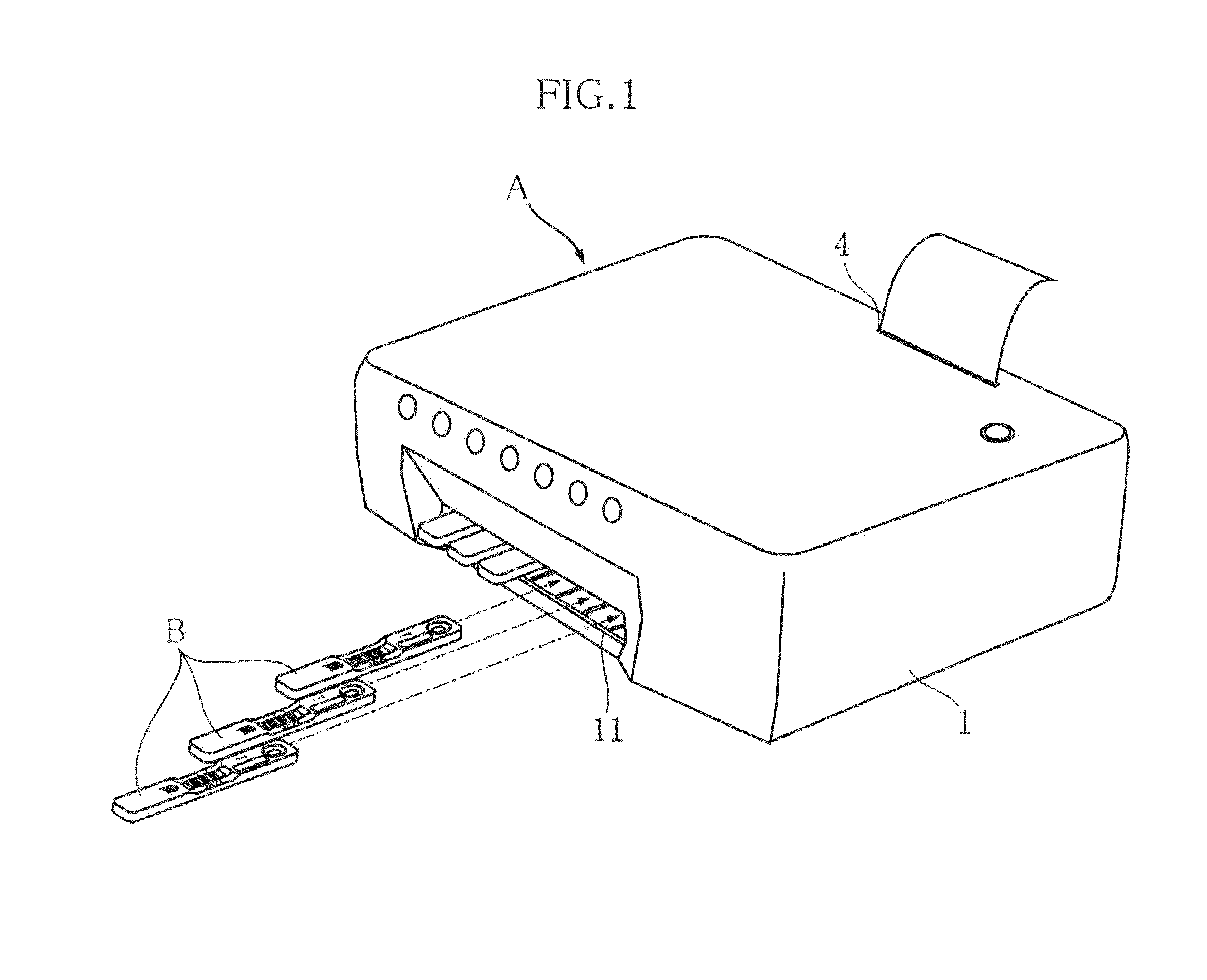
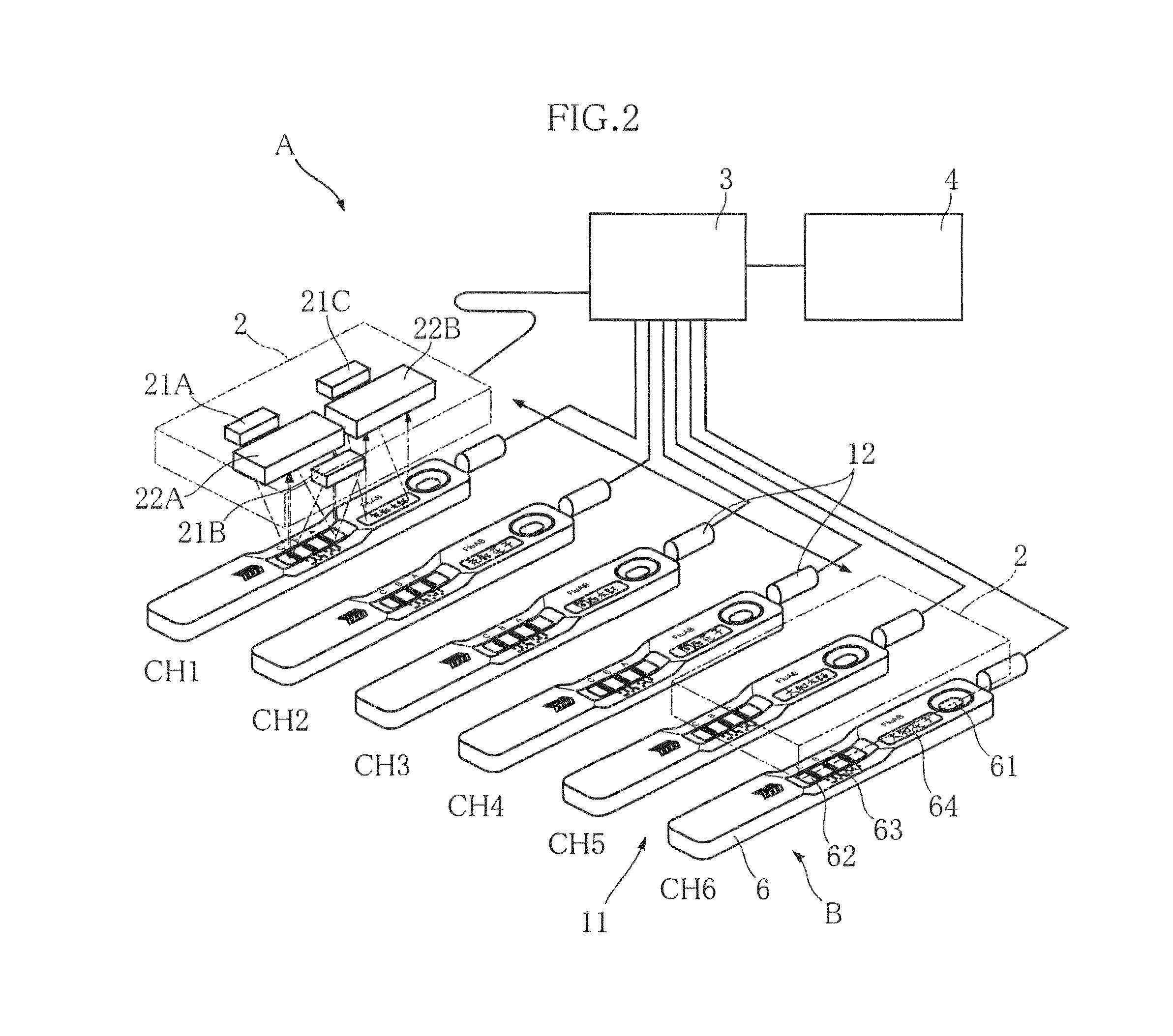
[0044]FIGS. 1 and 2 show an example of optical measurement apparatus according to the present invention. The optical measurement apparatus A of this embodiment includes a case 1, a reader 2, a controller 3 and a printer 4. The apparatus is designed to perform a test by immunochromatography by reading a test instrument B mounted to the apparatus. In FIG. 2, the illustration of the case 1 is omitted for easier understanding.

[0045]FIGS. 3 and 4 show a test instrument B to be mounted to the optical measurement apparatus A. In the test instrument B, a sample applied to the instrument reacts with a reagent. The test instrument has a shape and size suitable for the testing using the optical measurement apparatus A. The test instrument B includes a case 6, a carrier 7 and reagent retaining portions 8A, 8B, 8C to...


PUM

PropertyMeasurementUnit
angleaaaaaaaaaa
optical measurementaaaaaaaaaa
coloraaaaaaaaaa

Abstract

An object is to provide an optical measurement apparatus for performing an efficient test by optical measurement without incurring incorrect measurements.To this end, the measurement apparatus utilizes a test instrument mounted thereto and including a carrier with a reagent retaining portion for application of a sample. The measurement apparatus includes a reader for color development at the reagent retaining portion, and a controller for driving control of the reader and for required determination. The controller performs the determination by utilizing the data obtained by reading the color development of the reagent after a reaction completion period Tr1-Tr6 depending on the reagent and starting from the mounting of the test instrument. When detecting that the color development at the reagent retaining portion is completed before the lapse of the reaction completion period Tr1-Tr6 after the mounting of the test instrument, the controller stops the test for the test instrument.

Description

TECHNICAL FIELD[0001]The present invention relates to an optical measurement apparatus for performing a test by reading color development of a reagent by optical measurement.BACKGROUND ART[0002]In recent years, in hospitals and clinics or for home medical care, optical measurement apparatuses are often used as an apparatus for POCT (Point of Care Testing), which is the testing by people other than laboratory professionals. Examples of such optical measurement apparatuses include a clinical laboratory test apparatus (see e.g. Patent Document 2) for optically reading an urine test strip dipped in and pulled out of urine (see e.g. Patent Document 1) or a biochemical test piece to which blood serum / blood plasma extracted from blood is applied, and an apparatus for measuring a cuvette (see e.g. Patent Document 3) in which a liquid reagent is sealed.[0003]FIG. 7 shows an example of conventional optical measurement apparatus (see e.g. Patent Document 4). To the illustrated optical measurem...

Claims


Application Information

Patent Timeline
Patent Type & Authority Patents(United States)
IPC IPC(8): G01N21/84G01N33/52G01N21/25C12M1/34G01N33/558G01N33/543G01N33/50
CPCG01N21/8483G01N33/54386G01N33/558G01N21/25G01N33/52Y10T436/12Y10T436/11G01N21/84G01N33/54388
Inventor NAKAGAWA, TAKASHINAKAJIMA, SHINYAKASAI, TOKUOOHSHIRO, KYOUICHI
Owner ARKRAY INC
Why Eureka
Try Eureka