Automated sensor platform routing and tracking for observing a region of interest while avoiding obstacles

a sensor platform and automatic technology, applied in the direction of process and machine control, instruments, energy saving arrangements, etc., can solve the problems of aircraft limitation, aircraft cannot typically make sharp turns at the end of each scan, and the search area has to be oversized, so as to reduce the risk of crossing into the excluded area, reduce the path length, and reduce the redundancy

Active Publication Date: 2016-08-16
RAYTHEON CO
View PDF7 Cites 10 Cited by
  • Summary
  • Abstract
  • Description
  • Claims
  • Application Information

AI Technical Summary

Benefits of technology

[0008]The present invention provides for automated routing of a path for a sensor platform that projects a constant sensor footprint to the surface to observe a region of interest without crossing into an excluded area and to tracking that path. The path is routed such that all of the ROI except the excluded area is covered with a reduced path length and limited redundancy. The path is routed such that the risk of crossing into the excluded area is minimized. The sensor platform tracks the smooth path or a piecewise linear approximation of the path to capture a sequence of sensor outputs that cover all non-excluded regions of the ROI.

Problems solved by technology

Because of the kinematic constraints on an aircraft (e.g., its turn radius), the aircraft cannot typically make the sharp turns at the end of each scan.
The aircraft's tracking system will attempt to stay on the path but will inevitably overshoot the turns before returning to the path.
As a result, either portions of the region of interest may not be sensed or the search area has to be oversized to accommodate for the limitations of the aircraft.
This also increases the total path length of the aircraft.

Method used


Image

  • Automated sensor platform routing and tracking for observing a region of interest while avoiding obstacles
  • Automated sensor platform routing and tracking for observing a region of interest while avoiding obstacles
  • Automated sensor platform routing and tracking for observing a region of interest while avoiding obstacles

Examples


Embodiment Construction

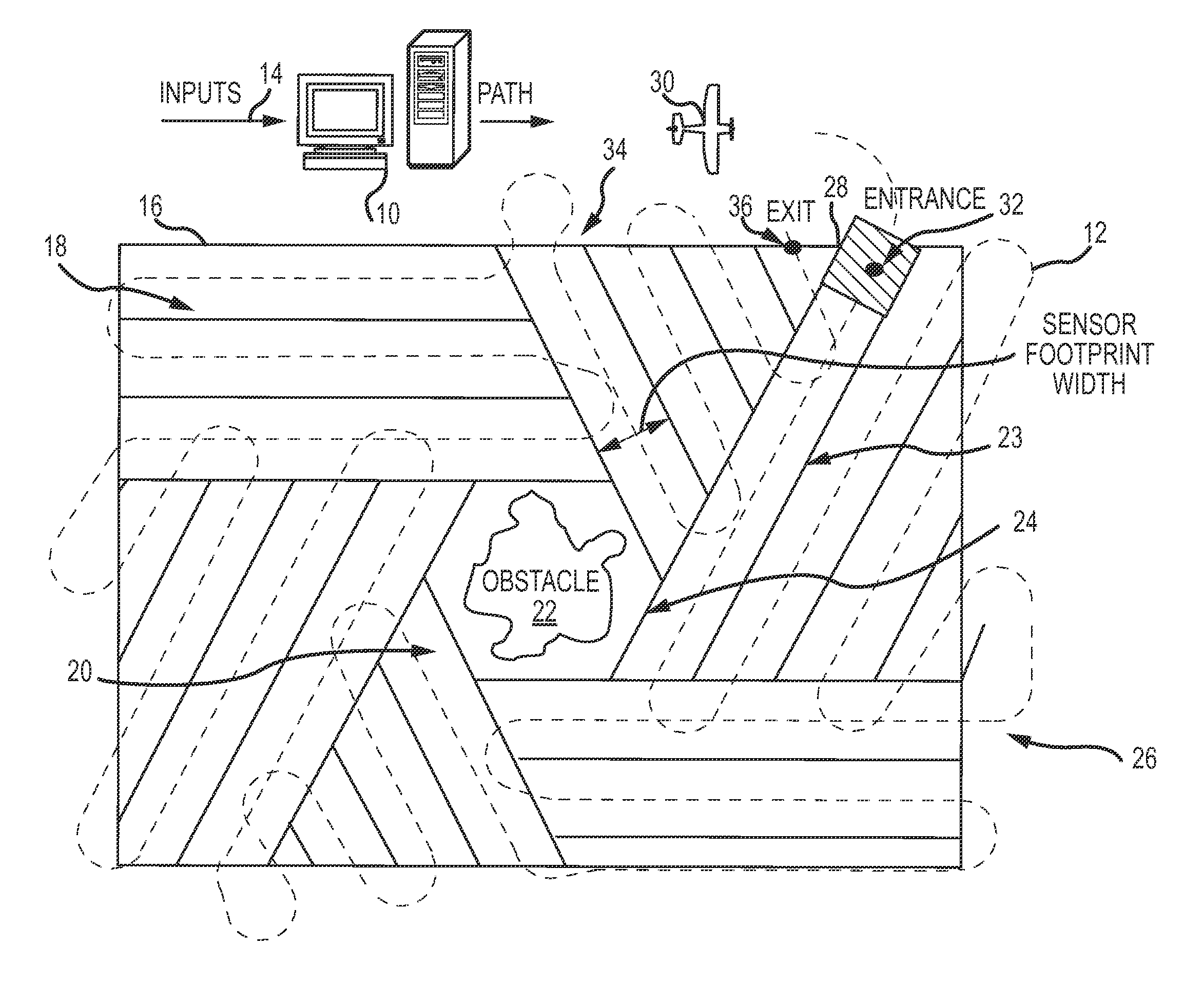
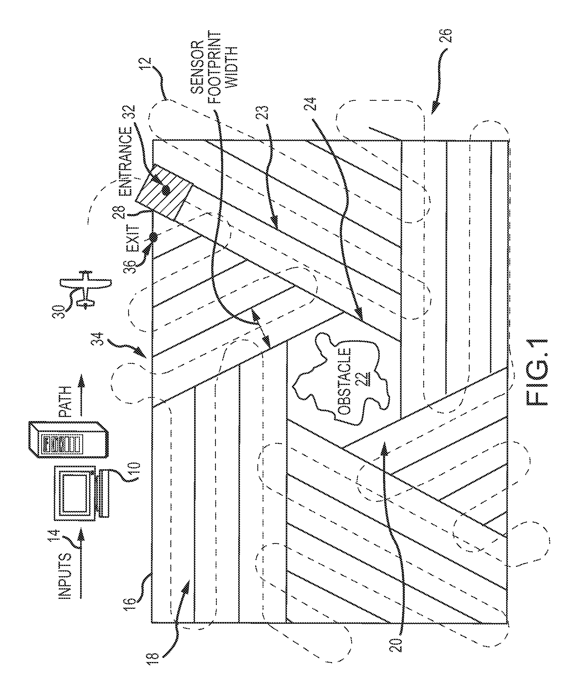
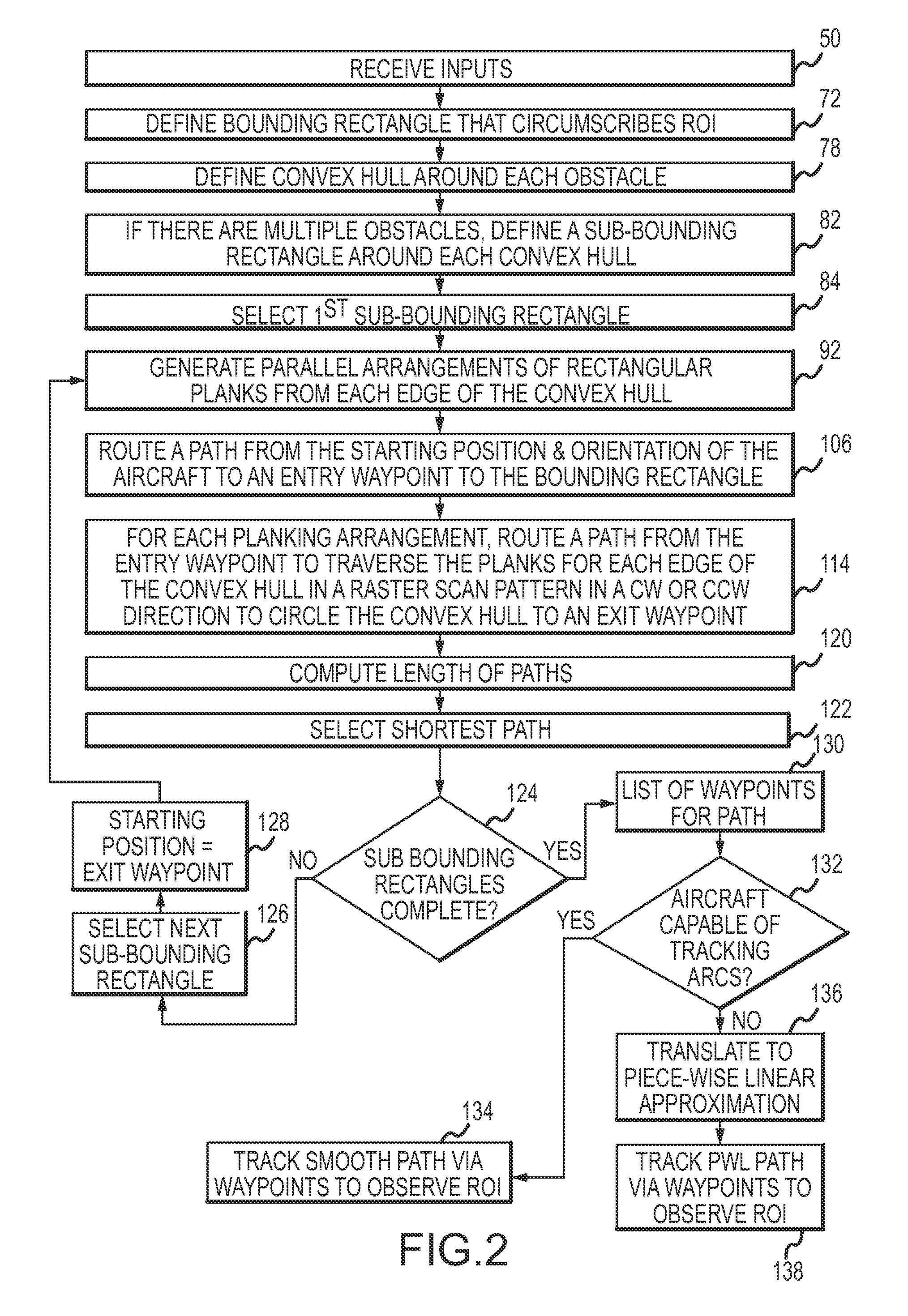
[0024]The present invention provides for automated routing of a path for a sensor platform that projects a constant sensor footprint to the surface to observe a region of interest without crossing into an excluded area and to tracking that path. The invention provides a particular methodology for routing the path for a sub-class of ROI observation defined by specific inputs and constraints on both the platform and the methodology. This approach avoids the tedious manual labor, redundancies and path length inefficiencies of the conventional raster scan techniques to route a path to observe a ROI having an excluded area. The sensor platform may be, for example, a manned or unmanned aircraft or a manned or unmanned underwater vehicle outfitted with a sensor.

[0025]The inputs include the ROI, an obstacle to avoid, a turn radius (minimum or preferred) for the sensor platform, a height above ground, a sensor footprint and the starting position and orientation of the sensor platform. The co...


PUM


Abstract

A path is automatically routed for a sensor platform that projects a constant sensor footprint to the surface to observe a region of interest without crossing into an excluded area and to tracking that path. The path is routed by defining a bounding region around the region of interest and defining a convex hull around an obstacle within the region of interest. A parallel arrangement of rectangular planks is generated from each edge of the convex hull out to the bounding region. The extent of each rectangular plank is bounded at one end by the intersection of the plank with the bounding region and at the other end by the intersection of the plank with an extension of a next edge of the convex hull. The path is routed to traverse the parallel arrangement of rectangular planks for each edge of the convex hull in a raster scan pattern and to circle the convex hull in a clockwise or counter-clockwise direction. The path is tracked and the surface below sensed to capture a sequence of sensor outputs that together cover the entire region of interest except the region excluded by the convex hull.

Description

BACKGROUND OF THE INVENTION[0001]1. Field of the Invention[0002]This invention relates to the routing and tracking of a sensor platform to observe a region of interest while avoiding obstacles.[0003]2. Description of the Related Art[0004]Manned and unmanned aircraft are used to observe and sense a region of interest on the ground to generate maps, surveil the region etc. In a typical scenario the aircraft maintains (or attempts to maintain) a fixed height above the ground and projects a constant sensor footprint onto the ground. The sensor footprint may be directly below the aircraft, forward or behind but is perpendicular to the flight path when projected onto the lateral-vertical plane of the aircraft.[0005]Typically, the aircraft is routed along a flight path that follows a raster-scan pattern back-and-forth to cover a rectangular region of interest. The aircraft senses a rectangular swath equal to the width of the sensor footprint. The swaths may overlap, say 10%. The flight pat...

Claims


Application Information

Patent Timeline
Patent Type & Authority Patents(United States)
IPC IPC(8): G01C21/20G08G5/00B64C39/02
CPCG08G5/003G01C21/20B64C39/024G05D1/0005G05D1/0094G05D1/0202B64C2201/12B64C2201/141B64U2101/00B64U2201/10
Inventor ROSENWALD, ROSS D.SAUNDERS, JEFFERY B.BOSSERT, DAVID E.DE SA, ERWIN M.
Owner RAYTHEON CO
Why Eureka
Try Eureka