Device for monitoring the state of a system

a technology of monitoring device and state, applied in the direction of visible signalling system, mechanical apparatus, instruments, etc., can solve the problem that the safety device cannot be disengaged, and achieve the effect of ensuring the state of the devi

Active Publication Date: 2016-08-23
EUCHNER GMBH & CO KG
View PDF10 Cites 0 Cited by
  • Summary
  • Abstract
  • Description
  • Claims
  • Application Information

AI Technical Summary

Benefits of technology

[0010]An object of the present invention is to provide an improved generic device, the operating states of which can be safely determined with the least possible effort and on an ongoing basis.
[0014]Advantageously, optical signaling by the device according to the invention is also possible, when the optical signaler is covered by the actuator in the state of the switch head and the actuator being in interaction with one another, in particular in contact with one another. In addition, the optional plurality of exit windows makes allows emitting the optical signal in different directions, for example simultaneously, both inside and outside of the safety device. At the same time, the optical signaler is disposed such that it is protected against contamination, damage and / or manipulation. In one embodiment, the entrance window and / or the exit window are flush with the surface surrounding them. Both contamination of and damage to the light-guide are thereby reliably prevented.
[0015]In one embodiment, the optical signaler is disposed on the switch head and at least one entrance window is disposed on the actuator such that, in the state of the device in which the switch head and the actuator are in interaction with one another, the optical signaler and the entrance window are disposed opposite one another. An advantageous coupling of the light emitted by the signaler is thereby ensured. At the same time, the optical signaler is covered by the actuator and is thereby protected against contamination and damage.
[0019]In one embodiment, the switch head is disposed, at least in part, in a groove of a profile, for example of an aluminum profile, as is used in industrialized building. The profile may be part of the device, but at the same time may also be part of the safety device by a corresponding mounting. In the state in which the switch head and the actuator are in interaction with one another, an light exit window of the optical signaler is covered by the actuator, which is likewise disposed, at least in part, in a groove of a profile. The arrangement in the groove of a profile ensures an especially space-saving construction. Moreover, not only the optical signaler, but also the switch head and, if applicable, the actuator, are disposed such that they are effectively protected against contamination and, in particular, against damage.

Problems solved by technology

The fixation is only removed, and the safety device can only be disengaged, when the machine is at a complete standstill.

Method used


Image

  • Device for monitoring the state of a system
  • Device for monitoring the state of a system
  • Device for monitoring the state of a system

Examples


Embodiment Construction

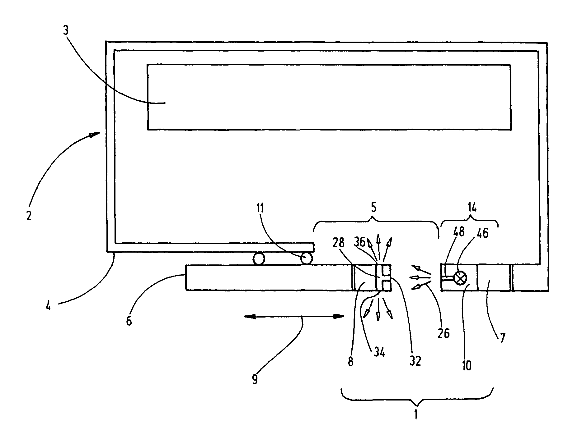
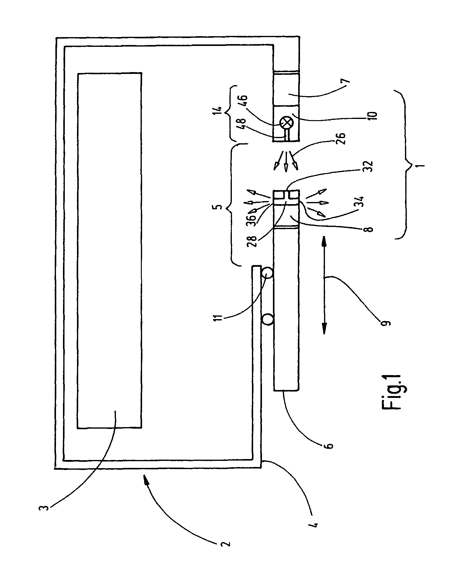
[0035]FIG. 1 is a top view schematically illustrating the overall assembly of a device 1 for monitoring the state of a safety device 2 for a machine 3, in particular of the engaged state of a safety door, with which a space separator can be locked, for example to protect the operator from being endangered by the machine 3 that is operating.

[0036]The safety device 2 has a first part 4, for example a frame. The first part 4 has an opening 5, which can be closed by a second part 6, for example by a safety door. The safety door can be moved relative to the first part 4 according to the double arrow 9 and may be movably mounted by mounting elements 11. Alternatively to being slid open and closed, the safety door may also be pivoted.

[0037]The device 1 preferably has a switch element 7 disposed on the fixed first part 4 of the safety device 2. The switch element comprises a switch head 10, as well as an actuator 8 preferably disposed on the movable second part 6. The actuator 8 can be brou...


PUM


Abstract

A device (1) monitors the state of a system (2), in particular safety switches for monitoring the closed state of safety equipment (2) of a machine (3). The device (1) is provided with a switch head (10) and an actuator (8), which can be brought into interaction with one another to control the device (1). The switch head (10) has an optical signaler (14) for optically signaling an operational state of the actuator (8) provided with a light-guide (28) having at least one entrance window (32) and at least one exit window (34, 36). In a state of the device (1) in which the switch bead (10) and the actuator (8) are interacting with one another, the light emitted by the signaler (14) enters, at least in part, via the at least one entrance window (32) and exits via the at least one exit window (34. 36).

Description

FIELD OF THE INVENTION[0001]The invention relates to a device for monitoring the state of a mechanism, in particular a safety switch for monitoring the engaged state of a safety device of a machine.BACKGROUND OF THE INVENTION[0002]Safety switches are used for monitoring the state of a safety device of a machine, for example, for monitoring the engaged state of a safety door of a safety enclosure for a machine tool or an industrial robot. When the safety device is in the engaged state, the safety switch can provide an enable signal for the operation of the machine. When the safety device is disengaged, the safety switch interrupts one or more electric circuits, for example, by an electrical contact pair that are actuated by positive locking or by an electronic switching element. The enable signal is then no longer provided. The associated machine can then be transferred to a safe operational state, for example it may be turned off, or the turning on of the machine may be prevented.[0...

Claims


Application Information

Patent Timeline
Patent Type & Authority Patents(United States)
IPC IPC(8): G08B5/00G08B5/36F16P3/08
CPCF16P3/08G08B5/36
Inventor GRIMM, ILO
Owner EUCHNER GMBH & CO KG
Why Eureka
Try Eureka