High energy laser target board apparatus

a laser target board and laser target technology, applied in the direction of optical radiation measurement, photometry using electric radiation detectors, instruments, etc., can solve the problems of inaccurate and unreliable indirect measurement of hel irradiance, inability to withstand the high intensity of hel beams, and inability to direct and accurately measure hel irradiance, etc., to achieve high optical power handling capability, flexible design, and direct and accurate measurement

Active Publication Date: 2016-08-23
TELEDYNE SCI & IMAGING
View PDF17 Cites 5 Cited by
  • Summary
  • Abstract
  • Description
  • Claims
  • Application Information

AI Technical Summary

Benefits of technology

[0012]A unique advantage of the invention is that both spatial and temporal intensity can be directly and accurately measured. For example, the laser target board apparatus may further include a processor configured to be connected to the at least one camera and configured to analyze temporal and spatial distribution of intensity of the received HEL beam based on data generated by the at least one camera based on the detected photons.
[0013]An advantage of the invention is that significantly high optical power handling capabilities are achieved by using an absorber as the barrier and probing directly small part of the photons in the beam that channels though the barrier. Because a significant percentage of the energy of the HEL beam is converted into heat and / or broadband or other forms of irradiance, the high energy photons do not damage the sensing elements. As such, the laser target board apparatus can withstand HEL beams up to a high laser damage threshold.
[0014]Furthermore, the laser target board apparatus is reusable and made of low-cost components. Also, the laser target board apparatus provides flexibility in design, has a scalable modular architecture, and can be calibrated and installed easily. In addition, the laser target board apparatus is light-weight and low-power, ideal for aircraft applications and airborne targeting practices for HEL weapons. Yet another unique advantage of the laser target board apparatus is that the accuracy of measurement is not impacted by test environment and flight aerodynamics.

Problems solved by technology

However, development of HEL devices has outpaced the development of HEL detector / sensor technology.
Indirect measurements of HEL irradiance (such as thermal sensors or remote optical / thermal imaging) have proven to be inaccurate and unreliable.
Photo detector arrays in direct path of HEL beams cannot withstand the high intensity of HEL beams.
Direct measurement has not been available for HEL irradiance on a moving target.
Because a target is subject to an extremely high temperature when exposed to HEL beams, the industry has not focused on development of target apparatuses under direct exposure to HEL beams.

Method used


Image

  • High energy laser target board apparatus
  • High energy laser target board apparatus
  • High energy laser target board apparatus

Examples


Embodiment Construction

[0024]Apparatus, systems and methods that implement the implementation of the various features of the present disclosure will now be described with reference to the drawings. The drawings and the associated descriptions are provided to illustrate some implementations of the present disclosure and not to limit the scope of the present disclosure. Throughout the drawings, reference numbers are re-used to indicate correspondence between reference elements. In addition, the first digit of each reference number generally indicates the figure in which the element first appears.

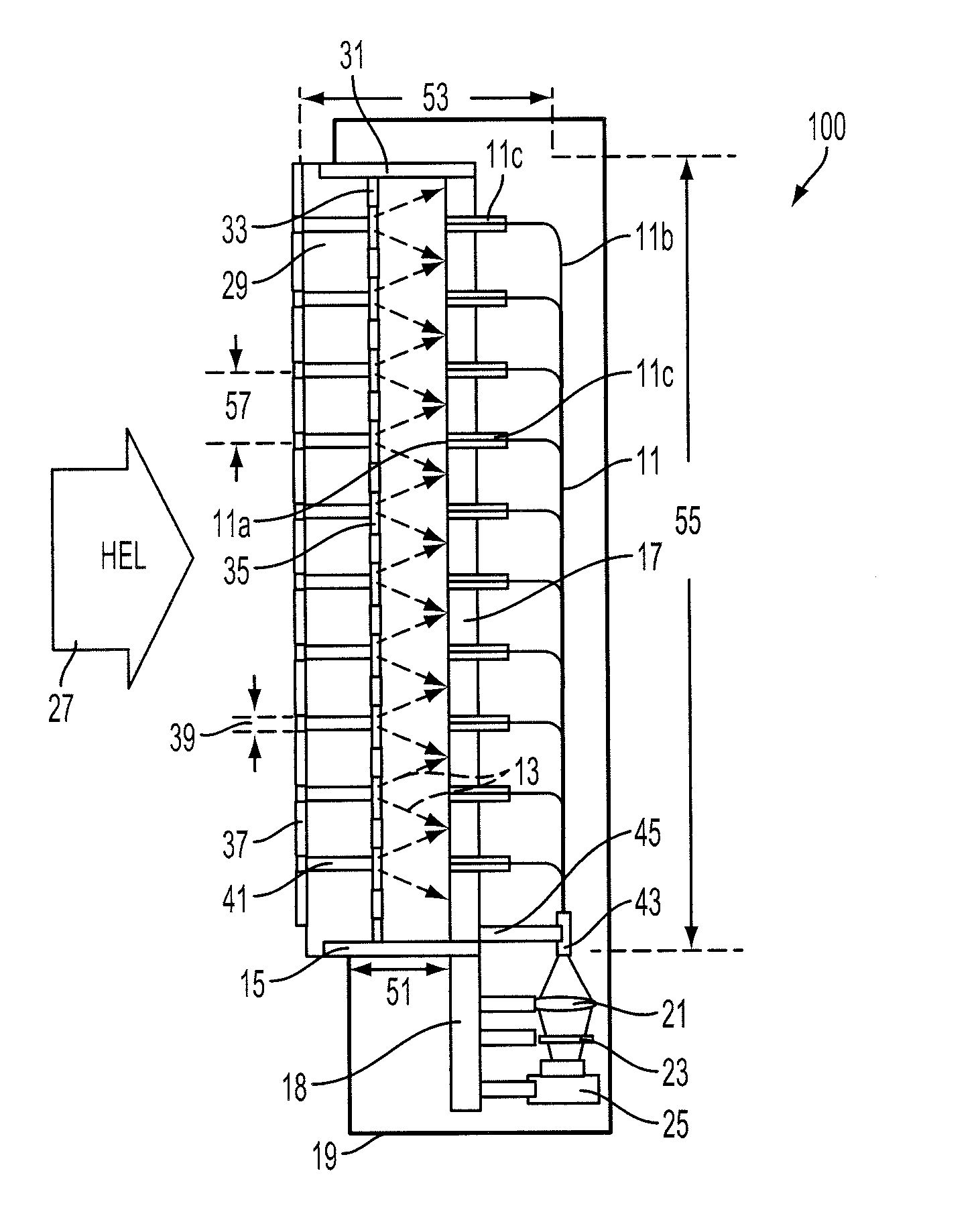
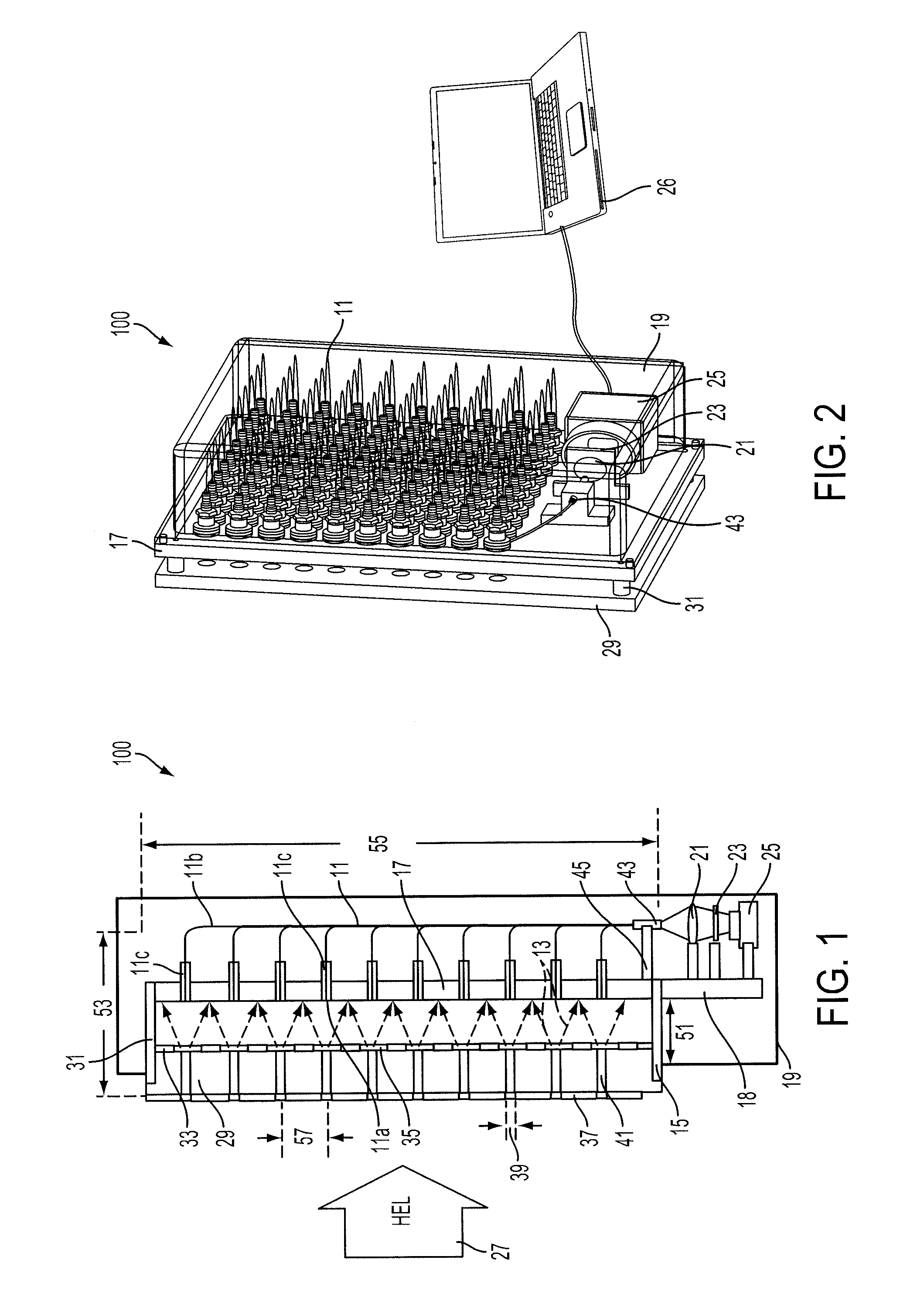
[0025]FIG. 1 is a cross-sectional view of a laser target board apparatus 100 for detecting spatial and temporal intensity distribution of high energy laser (HEL) beams according to certain embodiments of the present invention. FIG. 2 is a perspective view of the laser target board apparatus 100 shown in FIG. 1, according to certain embodiments of the present invention. The laser target board apparatus 100 detects an...


PUM


Abstract

A laser target board apparatus is provided for detecting spatial and temporal intensity distribution of high energy laser beams. The laser target board apparatus may include a panel having a plurality of openings and a plurality of optical rods placed therein. The laser target board apparatus may further have an optic fiber array positioned substantially parallel to and behind the panel and separated from the panel by a predetermined distance. At least one lens is configured to receive photons emitted from a second end of each optic fiber unit of the optic fiber array, and at least one camera is configured to detect the photons. A processor is configured to analyze temporal and spatial distribution of intensity of the received high energy laser beam based on data generated by the at least one camera.

Description

BACKGROUND[0001]1. Field[0002]The present disclosure relates to methods and systems for detecting and analyzing high energy laser beams.[0003]2. Description of the Related Art[0004]High Energy Laser (HEL) devices have been increasingly utilized in various applications. HEL weapons have been developed for destroying or burning a given target. HEL weapons have been increasingly utilized in moving military platforms (e.g., aircrafts, ships, trucks and unmanned aerial vehicle (UAV) or drones) to destroy targets such as missiles. However, development of HEL devices has outpaced the development of HEL detector / sensor technology. Therefore, there is a need in the art to determine temporal and spatial intensity of an HEL beam irradiating a target surface. Furthermore, there is a need in the art to determine temporal and spatial intensity in free space laser communication systems and optical power beaming systems.[0005]Indirect measurements of HEL irradiance (such as thermal sensors or remot...

Claims


Application Information

Patent Timeline
Patent Type & Authority Patents(United States)
IPC IPC(8): G01J1/42G01J1/04
CPCG01J1/0437G01J1/0474G01J1/4257G01J1/0425G01J1/0418G02B6/425G02B6/4296G02B6/00
Inventor GU, DONG-FENGWINKER, BRUCECHEN, YA-CHIMAHAJAN, MILIND
Owner TELEDYNE SCI & IMAGING
Why Eureka
Try Eureka