Rack server

a rack server and server technology, applied in the field of servers, can solve the problems of reducing the internal available pace, reducing the heat efficiency, and being flexible for the future, and achieve the effects of simplifying the infrastructure of conventional racks, reducing the amount of rack cables and boards, and substantial technical improvements

Active Publication Date: 2016-08-23
QUANTA COMPUTER INC
View PDF31 Cites 1 Cited by
  • Summary
  • Abstract
  • Description
  • Claims
  • Application Information

AI Technical Summary

Benefits of technology

[0023]In view of the foregoing, the technical solutions of the present disclosure result in significant advantageous and beneficial effects, compared with existing techniques. The implementation of the above-mentioned technical solutions achieves substantial technical improvements and provides utility that is widely applicable in the industry. Specifically, technical advantages generally attained, by embodiments of the present invention, include: the present disclosure, by using signal integration and adopting wireless transmission of the signals, simplifies the infrastructure of conventional racks, reduces the amount of rack cables and boards, and further improve the heat efficiency and reduces the design complexity and material cost.

Problems solved by technology

Inside conventional large rack servers, the communication and transmission of signals between boards are usually connected by cables; however, when the number of internal systems within a rack increases, so does the number of cables and boards; thereby resulting a decrease of the internal available pace; accordingly, such infrastructure of conventional racks limits the flexibility for future design, lowers the heat efficiency, increases the complexity in assembling and disassembling, and raises the costs for manpower and materials.
On the other hand, the infrastructure of conventional racks employs the cable as the media for transmitting and controlling signals, and hence, the planning complexity of signals is also quite high.
In view of the foregoing, there exist problems and disadvantages in the related art for further improvement; however, those skilled in the art sought vainly for a suitable solution.

Method used


Image

  • Rack server
  • Rack server
  • Rack server

Examples


Embodiment Construction

[0030]In the following detailed description, for purposes of explanation, numerous specific details are set forth in order to attain a thorough understanding of the disclosed embodiments. In accordance with common practice, the various described features / elements are not drawn to scale but instead are drawn to best illustrate specific features / elements relevant to the present invention. Also, like reference numerals and designations in the various drawings are used to indicate like elements / parts. Moreover, well-known structures and devices are schematically shown in order to simplify the drawing and to avoid unnecessary limitation to the claimed invention.

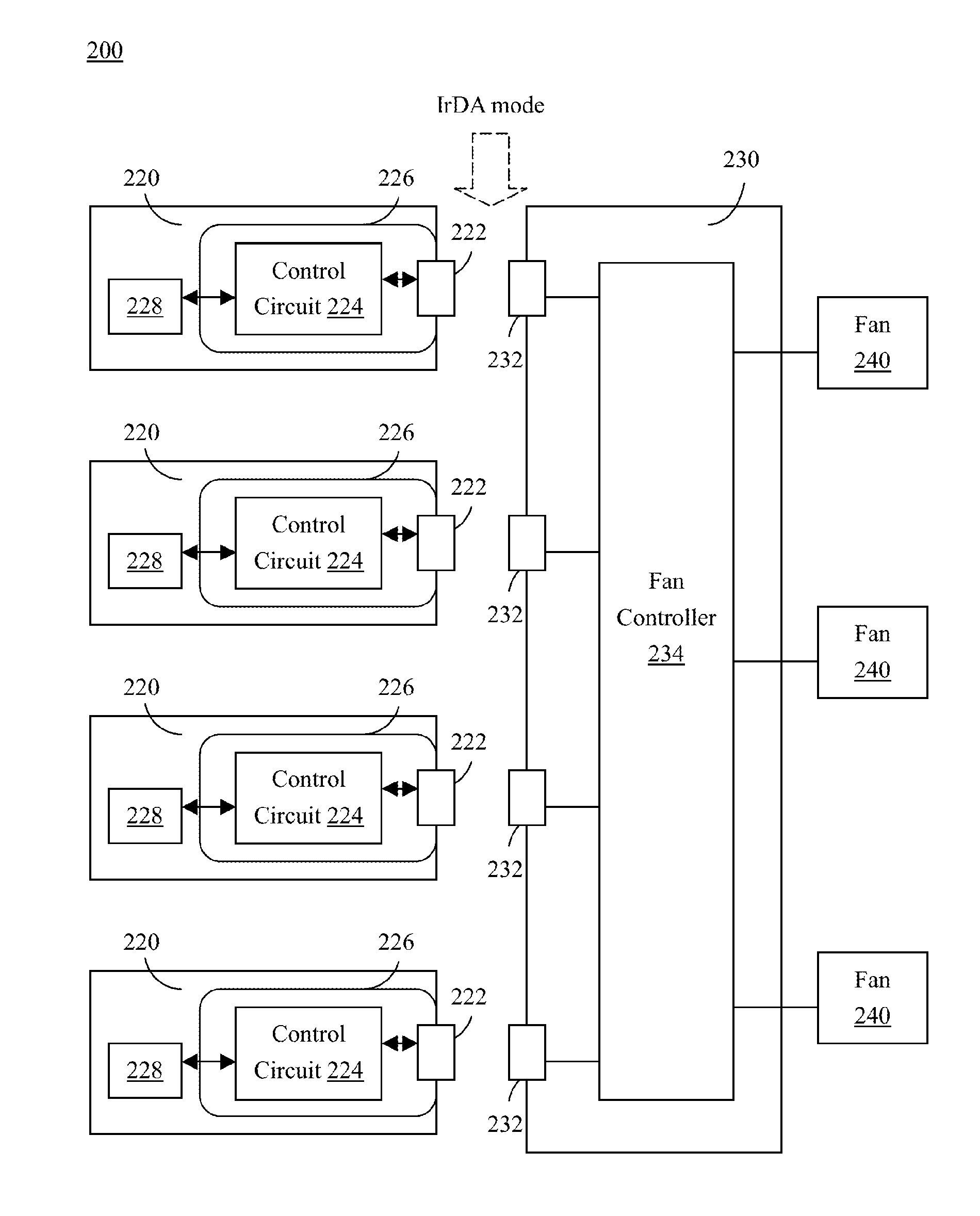
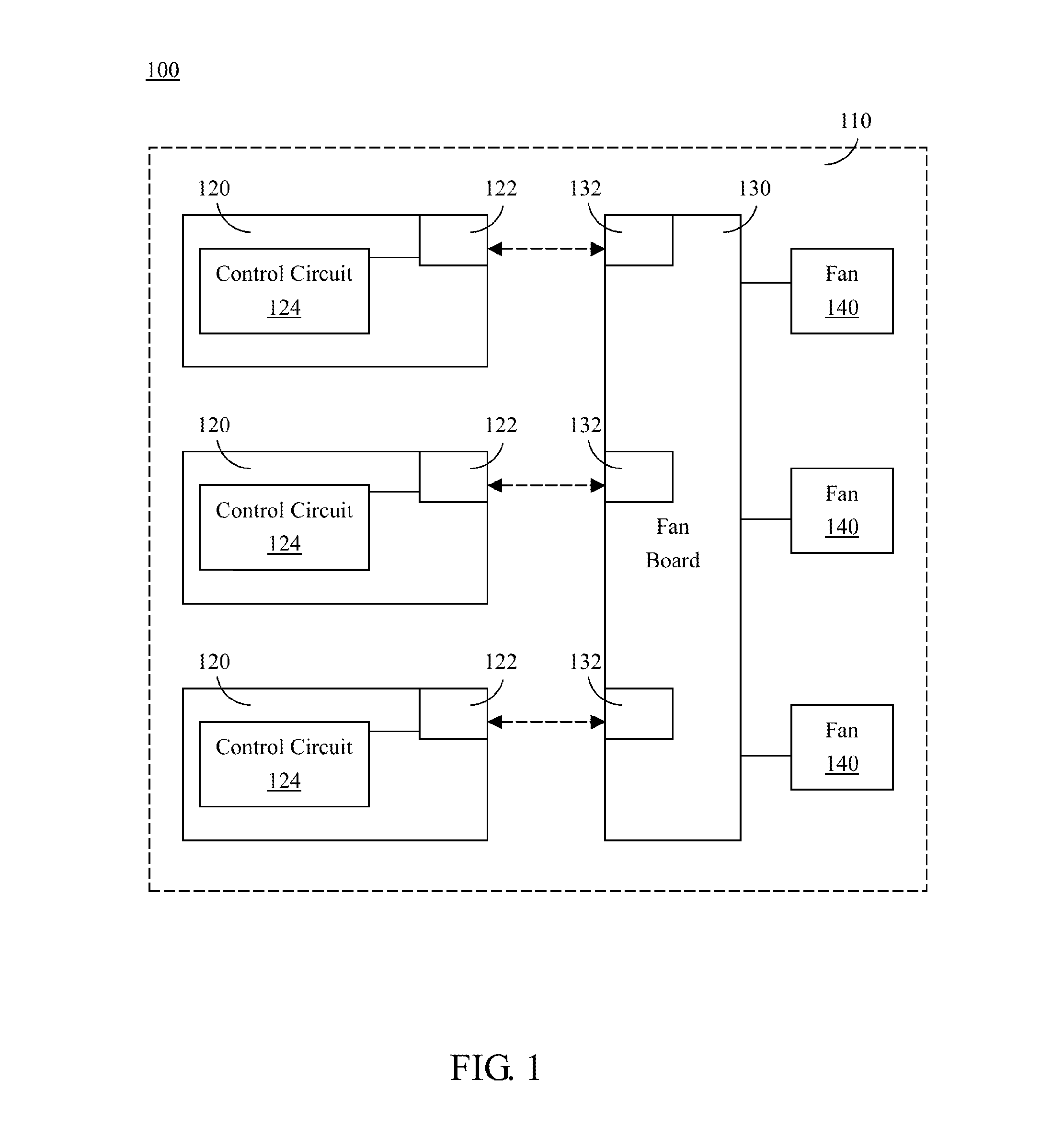
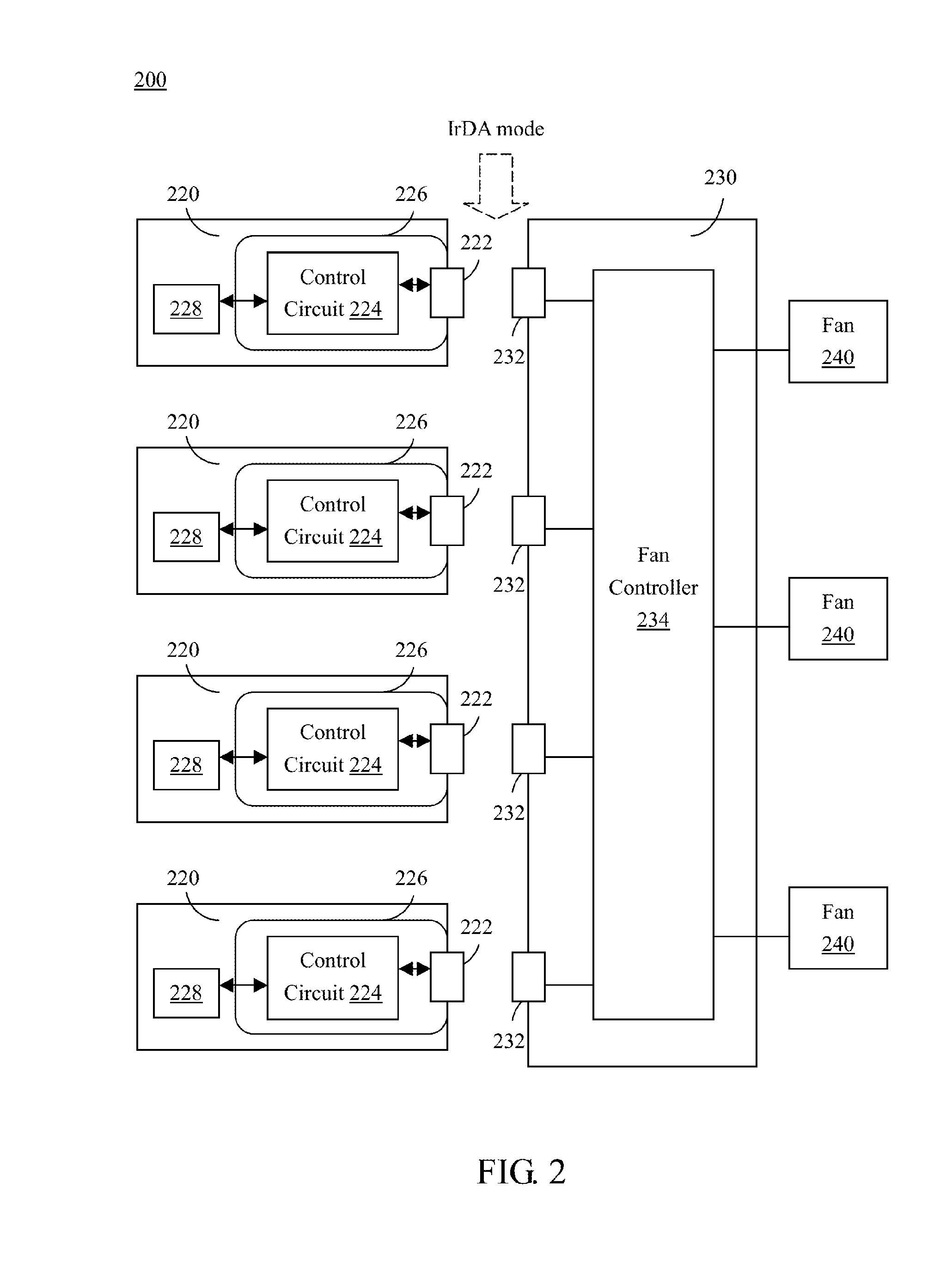
[0031]FIG. 1 is a schematic diagram illustrating the structure of a rack server 100 according to one embodiment of the present disclosure. As illustrated in FIG. 1, the rack server 100 comprises a rack 110, a plurality of system boards 120, a fan board 130 and a plurality of fans 140. In structure, the system boards 120, the fan b...


PUM


Abstract

Provided herein is a rack server including a rack, a plurality of system boards and a fan plate. The system boards are disposed within the rack, and each system board has a first wireless transceiver. The fan plate is also disposed within the rack, and the fan plate has a plurality of second transceivers, and the second transceivers are wirelessly connected to the first transceivers, respectively.

Description

RELATED APPLICATIONS[0001]This application claims priority to Taiwan Application Serial Number 102132834, filed Sep. 11, 2013, which is herein incorporated by reference.BACKGROUND[0002]1. Field of Invention[0003]The present invention relates to a server. More particularly, the present invention relates to a rack server.[0004]2. Description of Related Art[0005]Inside conventional large rack servers, the communication and transmission of signals between boards are usually connected by cables; however, when the number of internal systems within a rack increases, so does the number of cables and boards; thereby resulting a decrease of the internal available pace; accordingly, such infrastructure of conventional racks limits the flexibility for future design, lowers the heat efficiency, increases the complexity in assembling and disassembling, and raises the costs for manpower and materials.[0006]On the other hand, the infrastructure of conventional racks employs the cable as the media f...

Claims


Application Information

Patent Timeline
Patent Type & Authority Patents(United States)
IPC IPC(8): H04B10/00H04B10/80
CPCH04B10/803
Inventor JAU, MAW-ZANCHU, WEI-YIKO, TING-CHENLIANG, CHIA-MING
Owner QUANTA COMPUTER INC
Why Eureka
Try Eureka