Disc brake rotor

a disc brake rotor and disc brake technology, applied in the direction of brake types, brake elements, braking discs, etc., can solve the problems of slowing and/or stopping the rotation of the disc brake rotor, adding drag and noise that may be undesirable for some riders, and achieves excellent performance and causes added drag and nois

Inactive Publication Date: 2016-08-30
SHIMANO INC
View PDF6 Cites 3 Cited by
  • Summary
  • Abstract
  • Description
  • Claims
  • Application Information

AI Technical Summary

Benefits of technology

[0005]While disc brake systems provide excellent performance, frictional forces during braking generate heat, which should be dissipated. While some brake rotor designs have attempted to provide additional cooling, such designs can cause added drag and noise that may be undesirable for some riders.
[0006]The present disclosure is directed to providing a disc brake rotor for a bicycle that is configured to provide a desirable level of cooling to elements of the disc brake system while minimizing additional drag and noise.
[0008]By providing such a disc brake rotor, while the fin remains at rest (i.e., when the rotor remains relatively cool), aerodynamics of the bicycle remain unchanged, noise levels remain at a minimum, and extra air flow to the disc brake rotor is not provided. During braking, however, as the friction between the friction surface and braking elements generates heat, the temperature increase in the friction portion causes a related increase in the brake disc rotor itself, and the fin deflects relative to the temperature. Based on this deflection, additional airflow is provided to the brake disc rotor and greater cooling can be achieved.

Problems solved by technology

As the disc brake system is actuated, and the one or more pads are moved to be in contact with the disc brake rotor, frictional forces between the disc brake rotor and the one or more brake pads result in slowing and / or stopping of rotation of the disc brake rotor.
While some brake rotor designs have attempted to provide additional cooling, such designs can cause added drag and noise that may be undesirable for some riders.
During braking, however, as the friction between the friction surface and braking elements generates heat, the temperature increase in the friction portion causes a related increase in the brake disc rotor itself, and the fin deflects relative to the temperature.

Method used


Image

  • Disc brake rotor
  • Disc brake rotor
  • Disc brake rotor

Examples


Embodiment Construction

[0035]Selected embodiments will now be explained with reference to the drawings. It will be apparent to those skilled in the art from this disclosure that the following descriptions of the embodiments are provided for illustration only and not for the purpose of limiting the invention as defined by the appended claims and their equivalents.

[0036]Embodiments of the present invention are generally intended to provide variable cooling for a disc brake rotor as a temperature of the disc brake rotor changes during braking operations. Embodiments of the present invention will now be discussed with reference to the drawings.

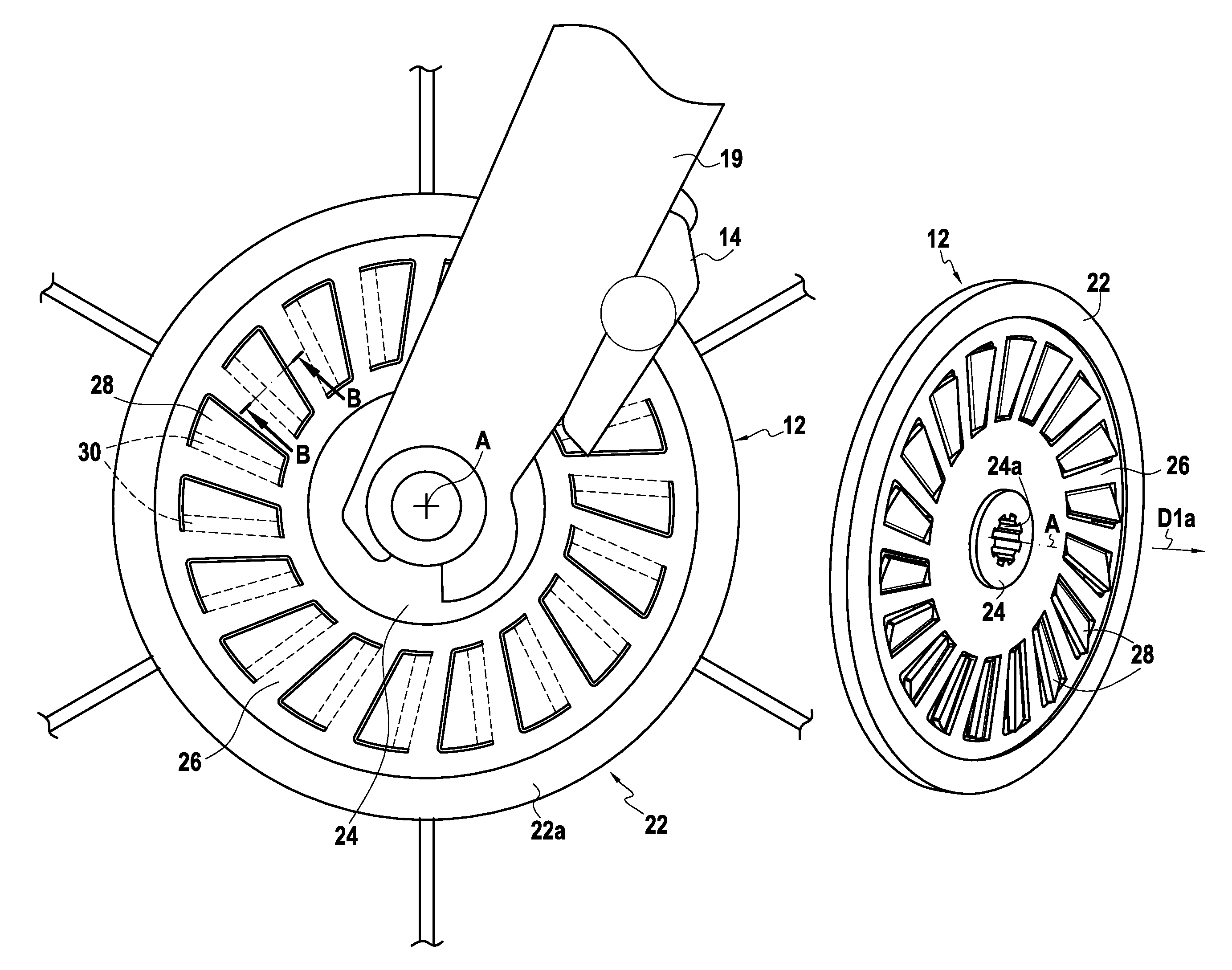
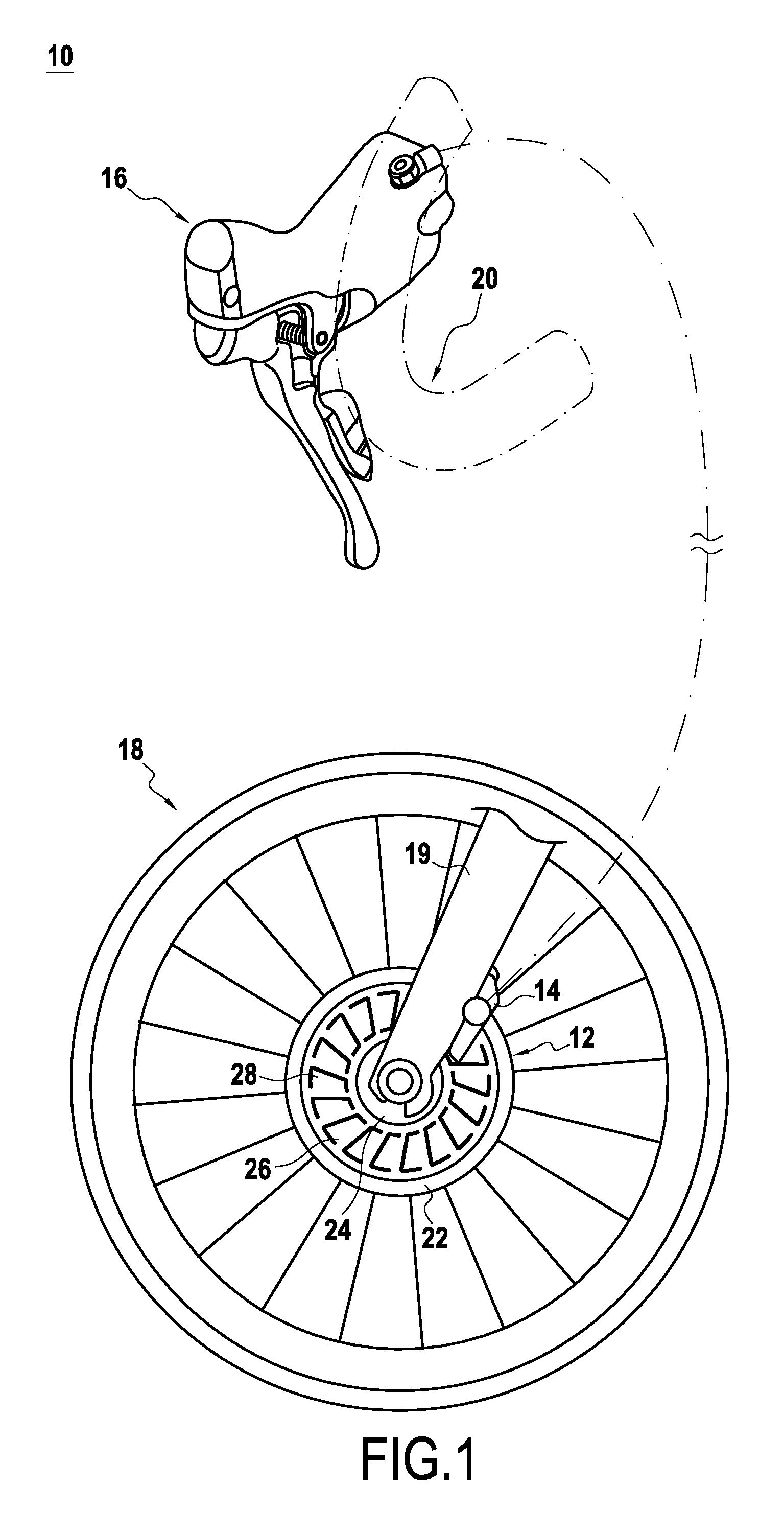
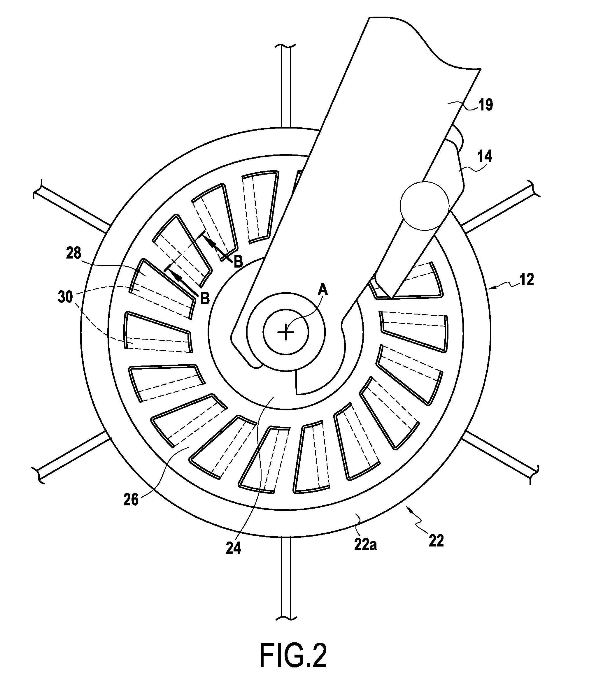
[0037]FIG. 1 shows an exemplary disc brake system 10 for bicycles. The disc brake system 10 includes a disc brake rotor 12, a disc brake caliper 14, and an operating (actuating) device 16. Additionally, other exemplary bicycle components e.g., a wheel 18, a front fork 19, a handlebars 20, etc., are shown for purposes of aiding understanding of the present invention.

[003...


PUM


Abstract

A disc brake rotor including a friction portion and a cooling fin located radially offset from the friction portion is provided. The cooling fin is configured to deflect due to a change in temperature in the friction portion.

Description

FIELD OF THE INVENTION[0001]The present invention relates to braking systems for bicycles and more particularly, to a disc brake rotor for a bicycle having improved cooling properties.BACKGROUND INFORMATION[0002]Disc brake systems can provide relatively large braking forces as compared to an amount of force applied in actuating the operating (actuating) device. In addition, disc brake systems also tend to provide relatively uniform service in varying weather conditions. For these and other reasons, disc brake systems for bicycles have increased in popularity in recent years.[0003]Disc brake systems include a disc brake rotor, a disc brake caliper including one or more brake pads, and an operating device configured to move the one or more brake pads toward the disc brake rotor. The operating device may be hydraulic, mechanical, electrical, and / or any other suitable actuator or combination thereof.[0004]As the disc brake system is actuated, and the one or more pads are moved to be in ...

Claims


Application Information

Patent Timeline
Patent Type & Authority Patents(United States)
IPC IPC(8): F16D65/12F16D65/847
CPCF16D65/128F16D65/847F16D65/125F16D2065/789
Inventor WATARAI, ETSUYOSHIGOTO, MASASHIEDAMURA, TAKUYA
Owner SHIMANO INC
Why Eureka
Try Eureka