Antenna apparatus and method for electronically pivoting a radar beam

a technology of electronic pivoting and radar beam, which is applied in the direction of radio wave reradiation/reflection, measurement devices, instruments, etc., can solve the problems of limited image resolution, comparatively geometrical large, and large space requirements for pivoted antennas, so as to improve usability in aircraft

Active Publication Date: 2016-08-30
EADS DEUT GMBH
View PDF16 Cites 0 Cited by
  • Summary
  • Abstract
  • Description
  • Claims
  • Application Information

AI Technical Summary

Benefits of technology

[0008]It is therefore an object of the invention to create a radar sensor having improved usability in aircraft.
[0009]The antenna apparatus according to the disclosed embodiments has the advantage that the analog beam formation can be easily carried out using known feed devices for radar antennas. The possibility of pivoting a radar beam in a first direction via analog beam formation and in a second direction via digital beam formation allows dispensing with complex mechanical devices for pivoting the entire radar sensor. It is possible to implement suitable feed devices having small space requirements and low weight in comparison to mechanical pivoting. In addition, such an antenna apparatus also allows the use of higher frequencies for the generated radar beam.
[0010]The angle of transmission and / or reception can be determined via a frequency of the radar signal. It is possible for feed devices for radar antennas to change the frequency of the radar signal that they provide quickly and precisely. This makes it possible to change the angle of transmission and / or reception efficiently using comparatively easily constructed and known feed devices.

Problems solved by technology

Known imaging obstacle radars that are, for example, sold by the company Honeywell, have limited image resolution due to the use of low frequencies and are comparatively geometrically large, since the antenna devices that are used particularly have large spatial dimensions due to the wavelengths of the radar waves that are used.
Radar systems that use higher frequency ranges to achieve a higher image resolution (for example, Sandblaster from Rockwell Collins) have mechanically pivoted antennas that also require a large amount of space.

Method used


Image

  • Antenna apparatus and method for electronically pivoting a radar beam
  • Antenna apparatus and method for electronically pivoting a radar beam
  • Antenna apparatus and method for electronically pivoting a radar beam

Examples


Embodiment Construction

[0028]Selected embodiments will now be explained with reference to the drawings. It will be apparent to those skilled in the art from this disclosure that the following descriptions of the disclosed embodiments are provided for illustration only and not for the purpose of limiting the invention as defined by the appended claims and their equivalents.

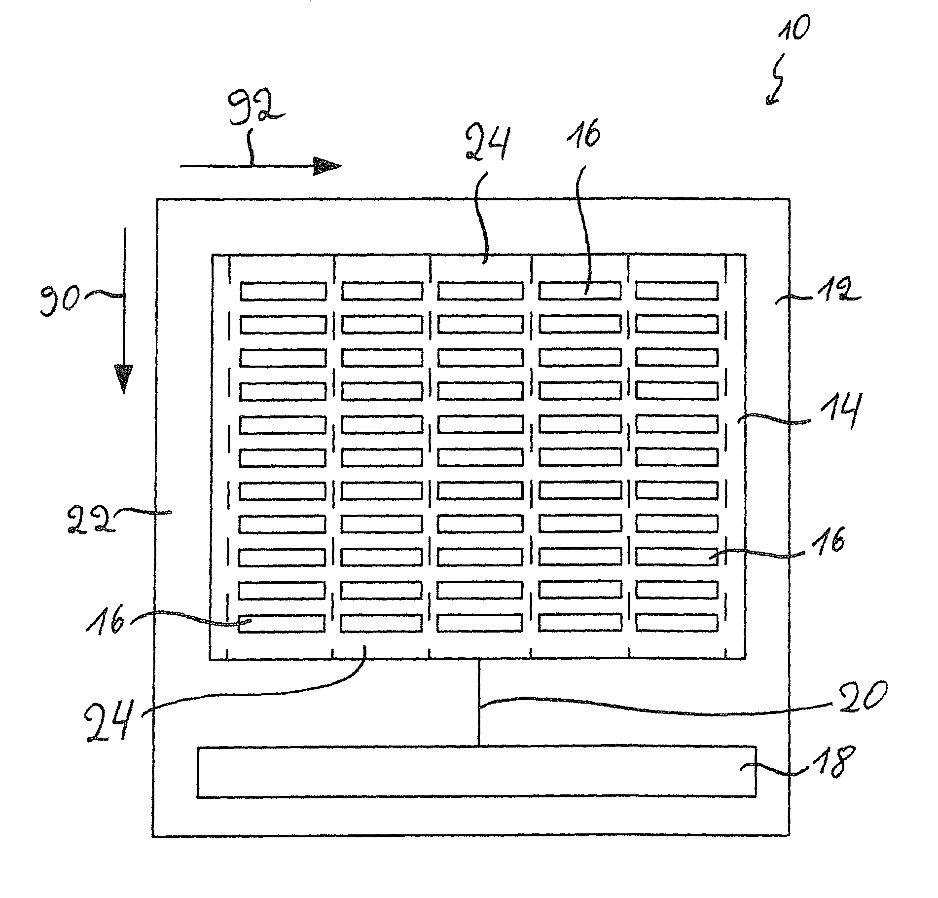
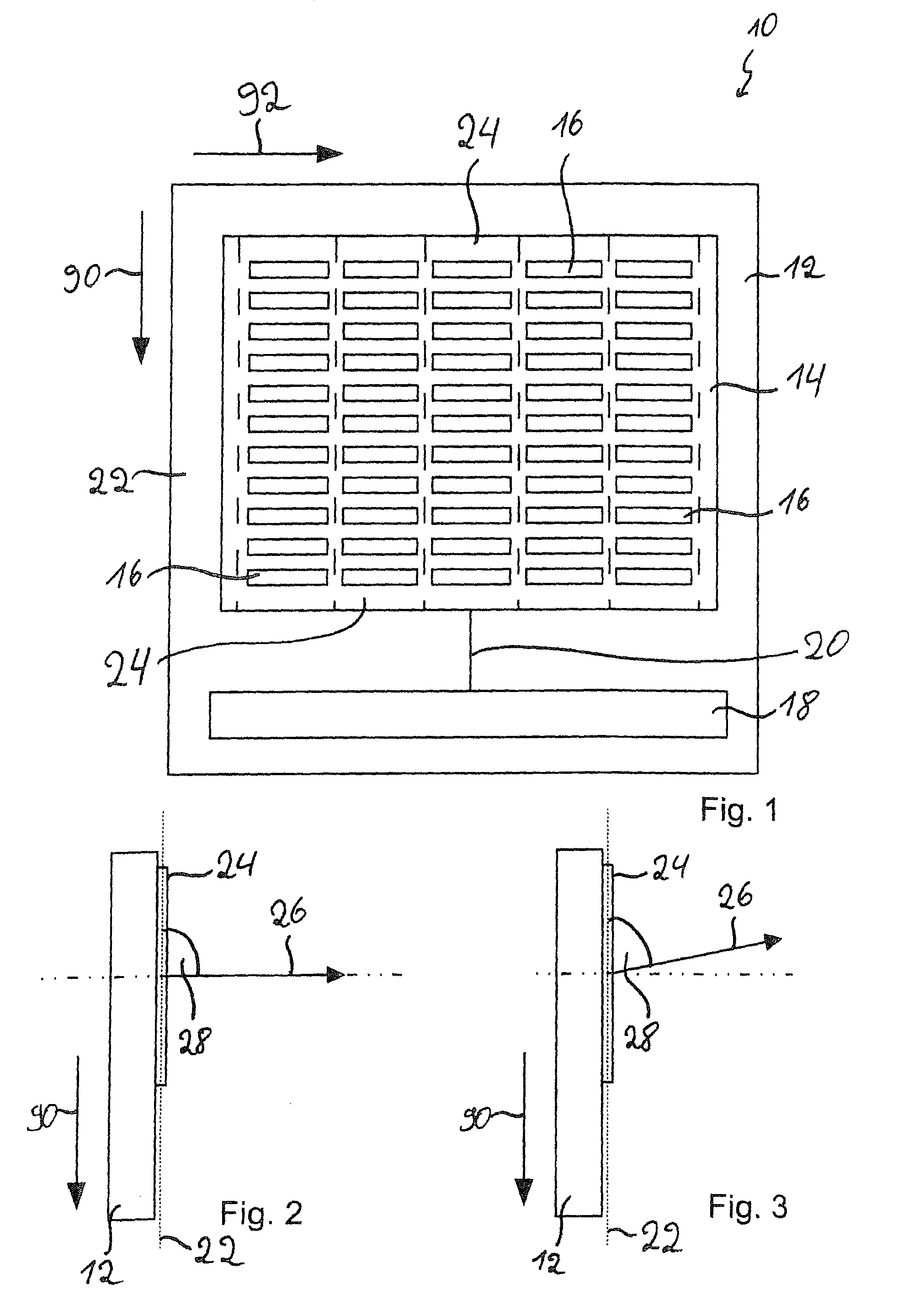
[0029]As shown in FIG. 1, an antenna apparatus 10 for a radar sensor has a frame 12 to which an antenna module 14 is attached. The antenna module 14 is adapted for radiating electromagnetic waves, in particular, high-frequency radar signals. In the present embodiment, the antenna module 14 is particularly useful for radiating electromagnetic waves having a frequency between 76 GHz and 81 GHz.

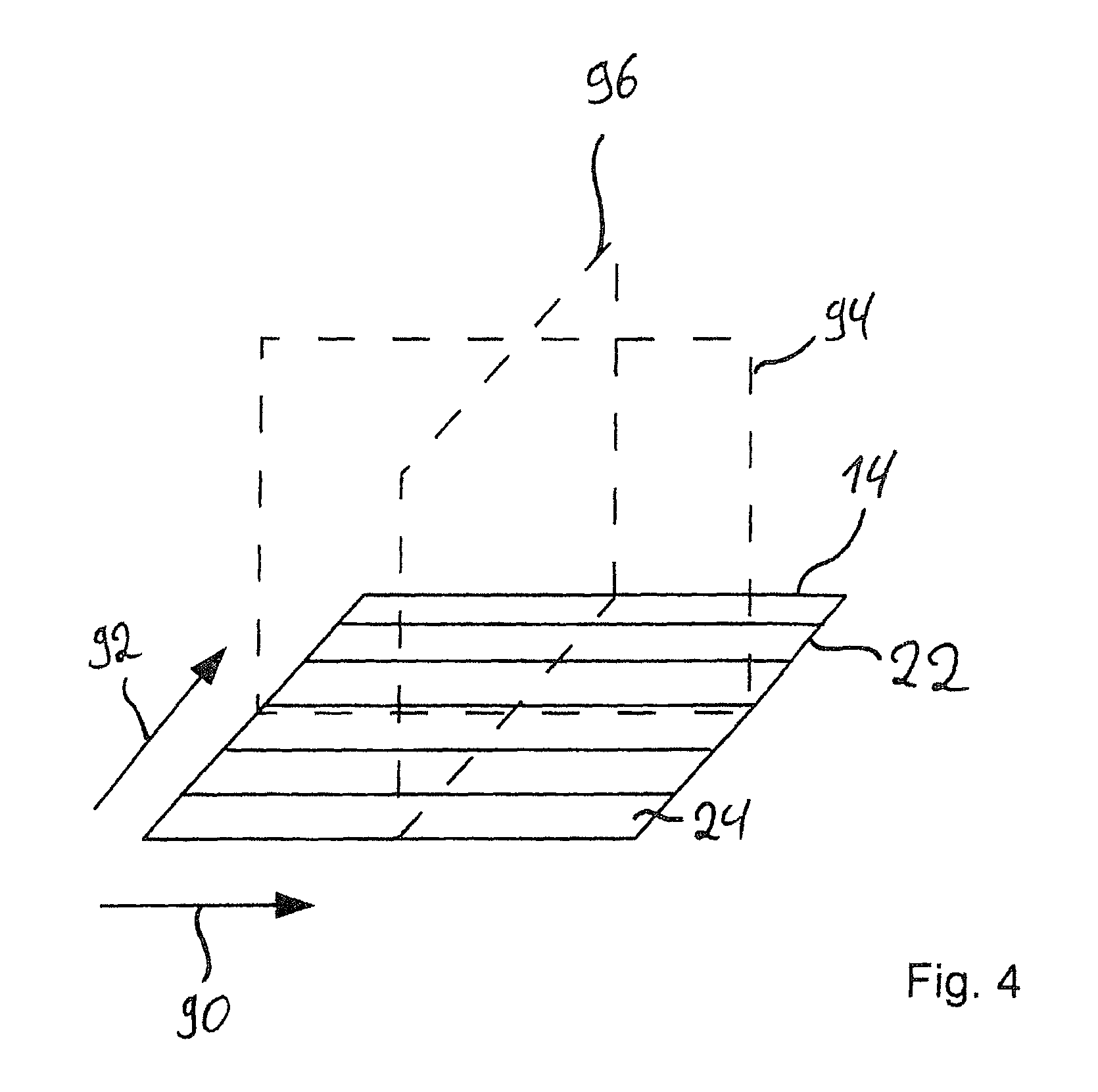
[0030]The antenna module 14 has a plurality of individual antenna devices 16 that are arranged in a flat grid. The grid is rectangular, a first dimension 90 and a second dimension 92 of the grid being perpendicular to each other. The individual anten...


PUM


Abstract

An antenna apparatus for a radar sensor having a plurality of individual antenna devices that interact through interference to generate and / or receive a radar beam at a predetermined angle of transmission and / or reception. The individual antenna devices are provided with a radar signal and are arranged such that a first angle of transmission and / or reception of the radar beam is determined via an analog beam formation and a second angle of transmission and / or reception of the radar beam is determined via a digital beam formation. The antenna apparatus further includes a feed device configured to generate the radar signal. In addition, the radar beam can be electronically pivoted. Also, an aircraft can include the antenna apparatus.

Description

CROSS-REFERENCE TO RELATED APPLICATIONS[0001]This application claims priority under 35 U.S.C. §119(a) to German Patent Application No. 10 2012 104 037.0, filed in Germany on May 8, 2012, the entire contents of German Patent Application No. 10 2012 104 037.0 are hereby incorporated herein by reference.BACKGROUND[0002]1. Field of the Invention[0003]The present invention relates to an antenna apparatus for a radar sensor that has a plurality of individual antenna devices that interact through interference to generate / and or receive a radar beam. The individual antenna devices are provided with a radar signal that is generated by a feed device. In addition, the application relates to a method for electronically pivoting a radar beam, wherein the radar beam is generated through interference of radar signals that are emitted by a plurality of individual antennas. Furthermore, the application relates to a radar sensor having such an antenna apparatus with which such a method can be carried...

Claims


Application Information

Patent Timeline
Patent Type & Authority Patents(United States)
IPC IPC(8): H01Q3/34G01S7/03H01Q3/22G01S13/94G01S13/42G01S7/06H01Q1/28G01S13/02G01S13/935
CPCH01Q1/28H01Q3/22H01Q3/34G01S7/03G01S7/062G01S13/426G01S13/94G01S2013/0245G01S13/935
Inventor ZIEGLER, VOLKERSCHULTE, BENEDIKT
Owner EADS DEUT GMBH
Why Eureka
Try Eureka