Supercharge Your Innovation With Domain-Expert AI Agents!

Cushion pin device for press

a technology of cushion pin and press, which is applied in the direction of presses, manufacturing tools, etc., can solve the problems of complicated logic valve control, and difficulty in dealing with both a material and an item of the panel, so as to prevent the inactivation of the press

Inactive Publication Date: 2016-09-06
HYUNDAI MOTOR CO LTD
View PDF9 Cites 0 Cited by
  • Summary
  • Abstract
  • Description
  • Claims
  • Application Information

AI Technical Summary

Benefits of technology

The present invention relates to a cushion pin device for a press that can hold an elastic blank and control its movement during blanking. The device uses a hydraulic control to accurately position the blank and prevent distortion on the finished panel. The goal is to improve the quality of the panel and productivity, while also saving on facility investment. Overall, the invention aims to prevent issues with the locking position of the cushion pad and enhance the quality of the finished panel.

Problems solved by technology

However, in such a conventional press device, hydraulic pressure supplied to the cushion cylinders respectively disposed at both sides of the cushion pin device are maintained to be same to control the operating position of the cushion cylinder, and as a result, locking move-up and lock holding of the cushion pad are performed, but a locking position of the cushion pad cannot be controlled under a condition to produce the press with a logic valve which is just turned on / off by only a single signal, and as a result, it is difficult to cope with both a material and an item of a panel.
Further, the locking position of the logic valve should be controlled by changing an output timing of a locking signal for each item (pressure / cushion stroke) and each SPM (production speed) of the molded panel, and as a result, it is complicated to control the logic valve and when a response speed of the logic valve is changed, a distribution of the locking position of the cushion pad is generated.
Therefore, the press is inactivated or a problem occurs in quality of the product panel which is press-molded.

Method used


Image

  • Cushion pin device for press
  • Cushion pin device for press
  • Cushion pin device for press

Examples


Embodiment Construction

[0039]Reference will now be made in detail to various embodiments of the present invention(s), examples of which are illustrated in the accompanying drawings and described below. While the invention(s) will be described in conjunction with exemplary embodiments, it will be understood that the present description is not intended to limit the invention(s) to those exemplary embodiments. On the contrary, the invention(s) is / are intended to cover not only the exemplary embodiments, but also various alternatives, modifications, equivalents and other embodiments, which may be included within the spirit and scope of the invention as defined by the appended claims.

[0040]An exemplary embodiment of the present invention will hereinafter be described in detail with reference to the accompanying drawings.

[0041]Prior to this, embodiments described in the present specification and configurations illustrated in the drawings are only the most preferred embodiment of the present invention and do not...


PUM

PropertyMeasurementUnit
forceaaaaaaaaaa
internal pressureaaaaaaaaaa
pressureaaaaaaaaaa

Abstract

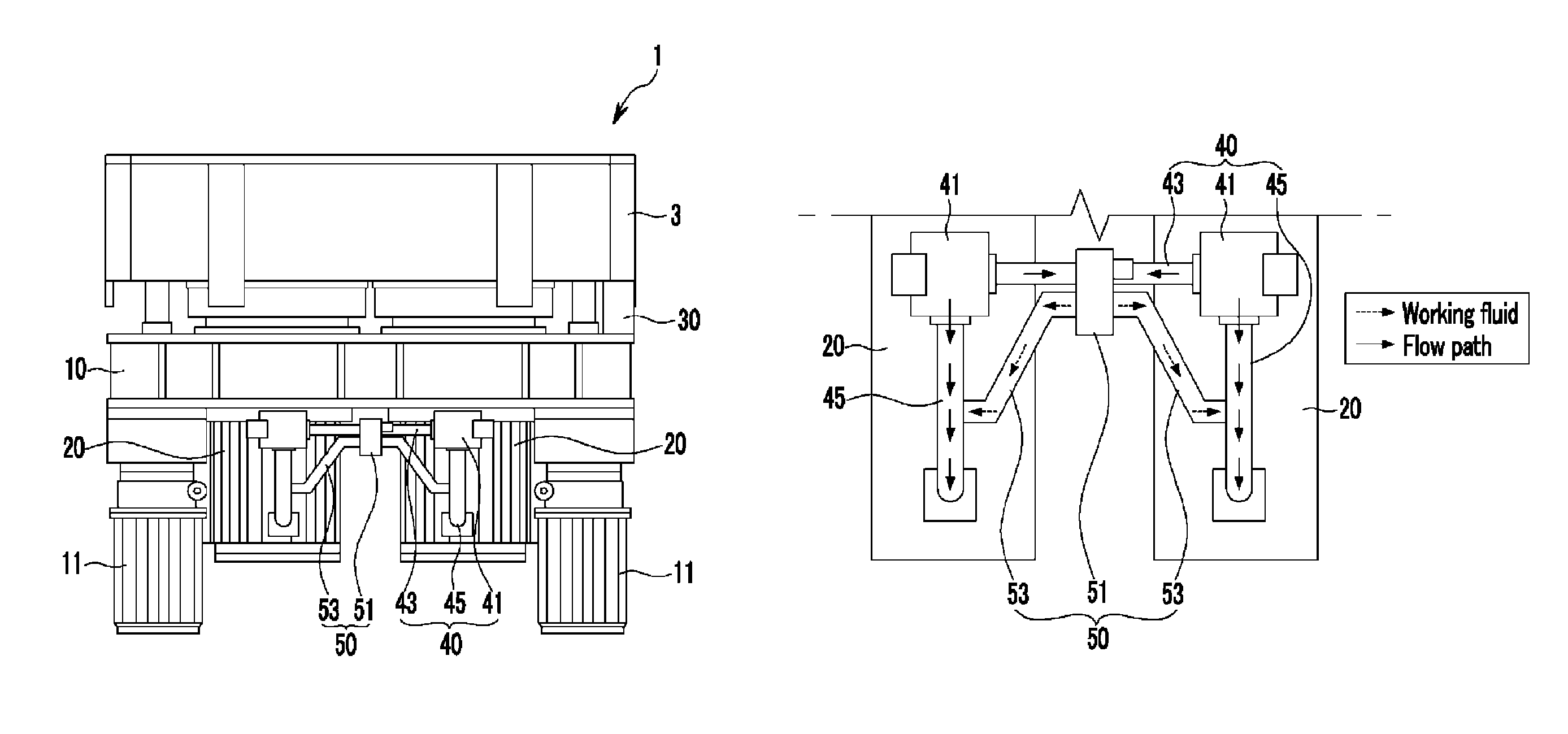
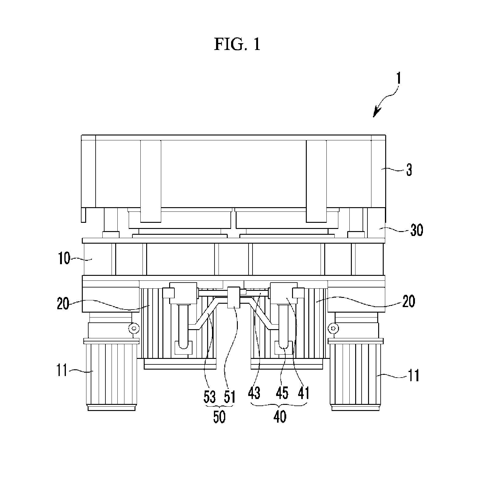
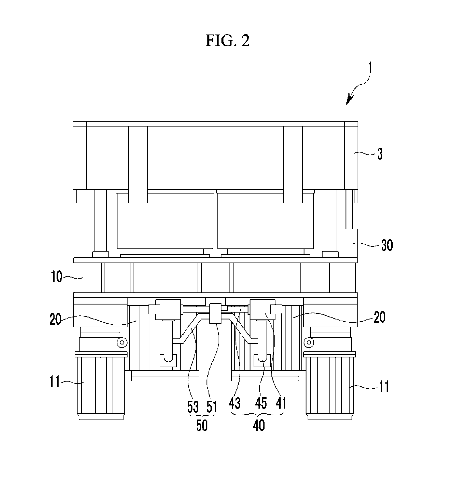
A cushion pin device for a press having a cushion pad in which a blank holder is seated on the top thereof outside a lower mold, and locks a blank holder to an upper mold while pressurizing an edge of a molded panel, includes: a cushion support disposed below the cushion pad, a cushion cylinder connected with a lower part of the cushion pad to move up or down the cushion pad from the cushion support, a linear scale mounted between the cushion pad and the cushion support to measure the position of the cushion pad, a main pressure control unit that keeps internal pressure of each cushion cylinder similarly, and a sub pressure control unit that is interconnected with the main pressure control unit so as to control the locking position of the cushion pad when each cushion cylinder operates.

Description

CROSS-REFERENCE TO RELATED APPLICATION[0001]The present application claims priority to Korean Patent Application No. 10-2013-0106560 filed on Sep. 5, 2013, the entire contents of which is incorporated herein for all purposes by this reference.BACKGROUND OF THE INVENTION[0002]1. Field of the Invention[0003]The present invention relates to a cushion pin device for a press, and more particularly, to a cushion pin device for a press that moves up and down a cushion pad on which a blank holder is seated so as to generate blanking holding force on a panel which is press-molded, controls lock holding and move-up of the cushion pad through hydraulic control, and controls a locking position degree.[0004]2. Description of Related Art[0005]In general, an automaker produces an automobile by assembling 20 to 30 thousand parts several times.[0006]In particular, as a first step of an automobile manufacturing process, product panels are produced through various types of press devices and thereafter...

Claims


Application Information

Patent Timeline
Patent Type & Authority Patents(United States)
IPC IPC(8): B21D24/14B21D24/08B30B15/06B21D24/02
CPCB21D24/14B21D24/08B21D24/02B30B15/061
Inventor KIM, JU YOUNG
Owner HYUNDAI MOTOR CO LTD
Features
  • R&D
  • Intellectual Property
  • Life Sciences
  • Materials
  • Tech Scout
  • Unparalleled Data Quality
  • Higher Quality Content
  • 60% Fewer Hallucinations
Learn More