Modular electrical connector

a technology of modular electrical connectors and connectors, applied in the direction of coupling devices, two-part coupling devices, electrical apparatus, etc., can solve the problems of time-consuming and expensive electrical system insulation methods, wires must fit within, and the installation of electrical components is one time-consuming and expensive task during building construction and renovation, so as to improve the ease and speed of electrical component installation.

a technology of modular electrical connectors and connectors, applied in the direction of coupling devices, two-part coupling devices, electrical apparatus, etc., can solve the problems of time-consuming and expensive electrical system insulation methods, wires must fit within, and the installation of electrical components is one time-consuming and expensive task during building construction and renovation, so as to improve the ease and speed of electrical component installation.

US9437978B2Active Publication Date: 2016-09-06GREEN WESLEY G

Image

  • Modular electrical connector
  • Modular electrical connector
  • Modular electrical connector

Examples


Embodiment Construction

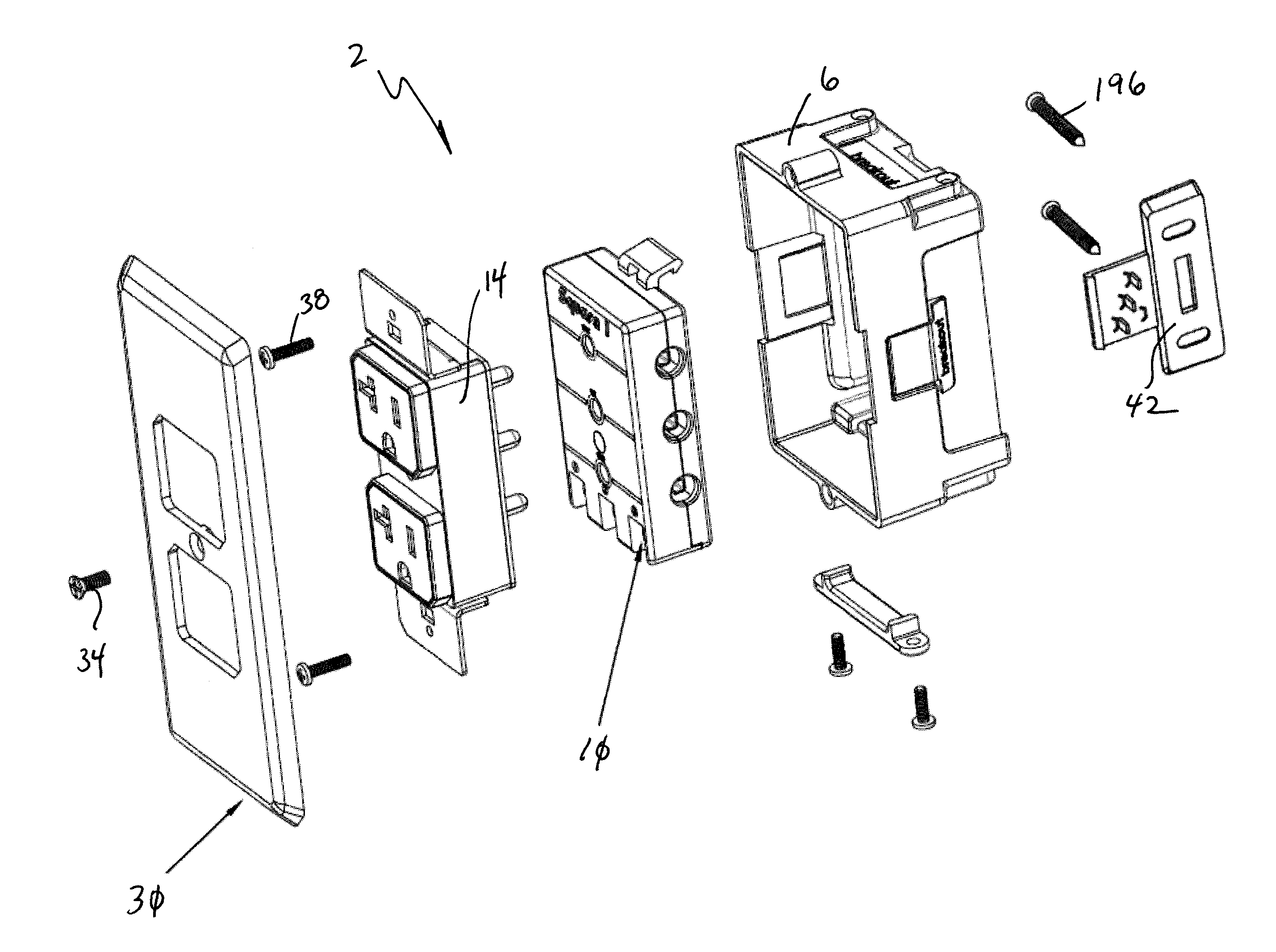
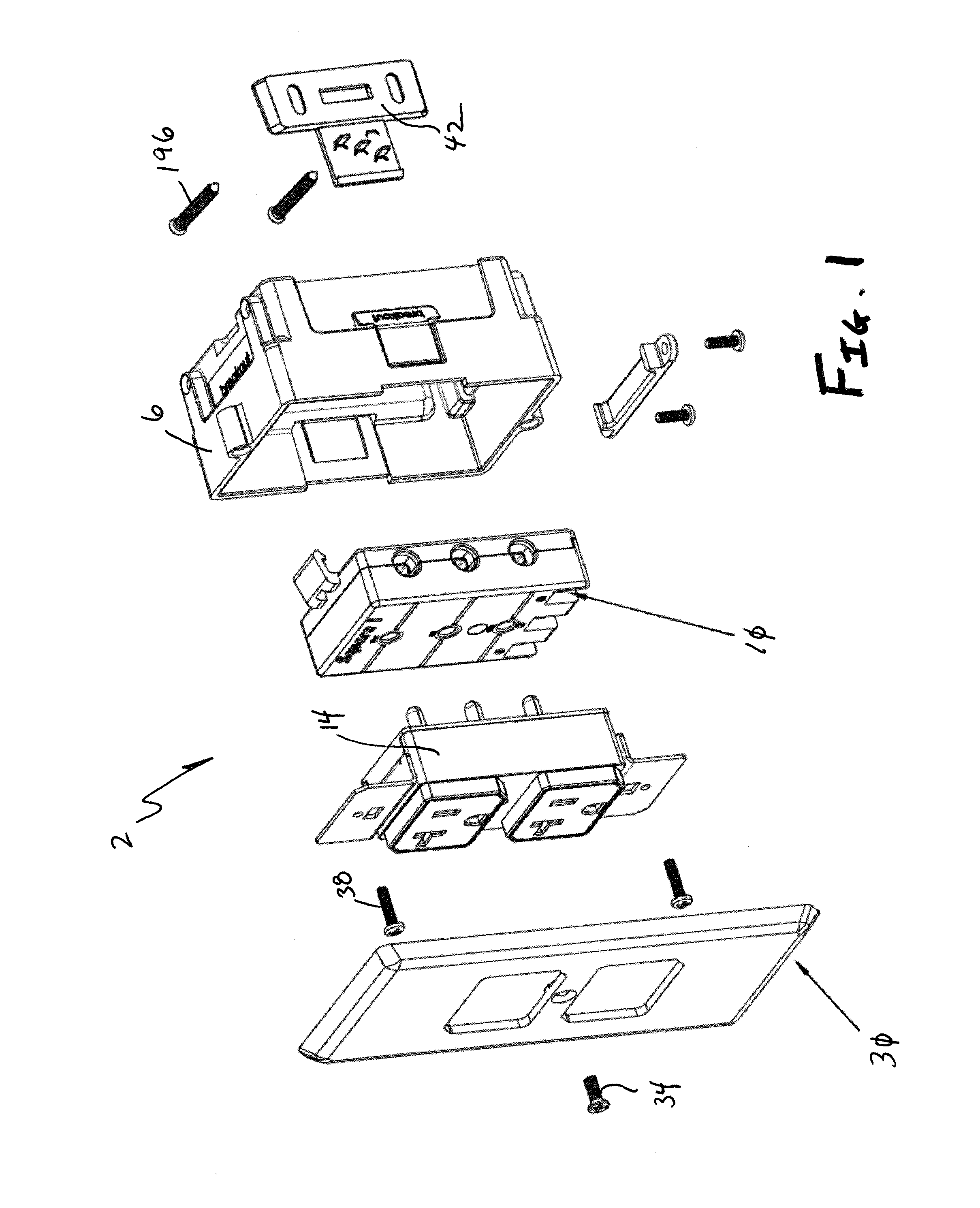
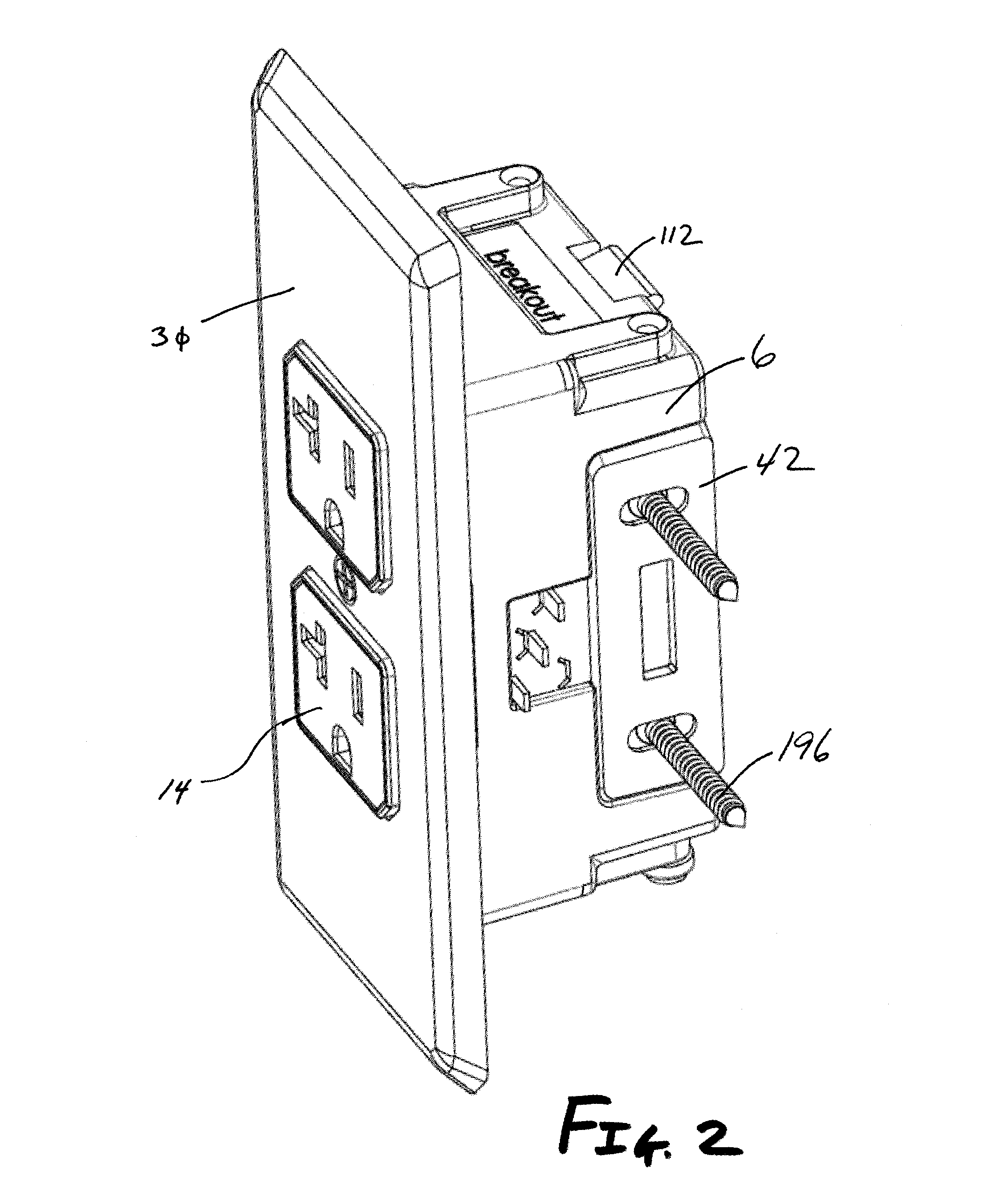
[0164]FIGS. 1 and 2 show the modular electrical connector system 2 of one embodiment of the present invention that includes a junction box 6 that receives the module 10 and an electrical component 14. Although the electrical component 14 is shown as an outlet, those of ordinary skill in the art will appreciate the module 10 of some embodiments of the present invention is able to receive other electrical components 14, such as switches. Also, as described above, the module 10 may be sized to receive multiple electrical components. Further, although a traditional 120 V outlet is shown, a larger outlet, such as a 220 V, commonly used in ovens and clothes dryers, may be accommodated.

[0165]In operation, the module 10 is interconnected to a common wire cable 18 (see FIG. 12) and then interconnected to the junction box 6. Thereafter, the electrical component 14 is selectively interconnected via prongs 22 to receptacles 28 of the module 10. The electrical component 14 is interconnected to t...


PUM


Abstract

A system for providing electrical energy and related components is provided. More specifically, a universal module that is adapted to fit within a junction box commonly found in building construction is provided. The wire cable associated with a dwelling, for example, is interconnected to the module, which provides a plurality of locations for receipt of corresponding electrical connectors of an outlet or switch. The modules quickly and safely receive an electrical component, which reduces time and associated costs related to electrical system installation, repair, or modification.

Description

[0001]This application claims the benefit of U.S. Provisional Patent Application Ser. No. 62 / 010,035, filed Jun. 10, 2014, the entire disclosure of which is incorporated by reference hereinFIELD OF THE INVENTION[0002]Embodiments of the present invention are generally related to electric circuit components and, more particularly, to modules that interconnect electrical components such as outlets, switches, receptacles, and other devices for selectively providing or controlling electricity to a power source.BACKGROUND OF THE INVENTION[0003]Electrical system installation is a one time consuming and expensive task performed during building construction and renovation. The process starts with attaching junction boxes on exposed wall studs at pre-determined locations throughout the building. The junction boxes will eventually house electrical components such as outlets and switches. Next, the electrician routes wire cable from a circuit breaker box to the junction boxes and, if required, ...

Claims


Application Information

Patent Timeline
06 Sep 2016
Publication
US9437978B2
IPC
H01R24/78; H01R13/652; H01R13/717; H01R13/74; H01R25/00; H01R13/66; H01R103/00
CPC
H01R13/652; H01R13/7175; H01R13/743; H01R24/78; H01R25/006; H01R13/6691; H01R2103/00
Inventors
GREEN, WESLEY G.