Plug connector assembly having improved anti-EMI performance

a technology of anti-emi and connectors, applied in the direction of coupling device connections, electrical apparatus, coupling devices, etc., can solve the problems of poor anti-emi performance and metal shell strength, and achieve good anti-emi performance, good sealing performance, and improved structural strength

Active Publication Date: 2016-09-20
FOXCONN INTERCONNECT TECH LTD
View PDF12 Cites 11 Cited by
  • Summary
  • Abstract
  • Description
  • Claims
  • Application Information

AI Technical Summary

Benefits of technology

[0007]An object of the present invention is to provide a plug connector assembly without gaps between connecting portions of metal shells and having good anti-EMI performance.
[0010]According to the present invention, both of the first and the second shells have a closed circumference. Therefore, the plug connector assembly has good seal performance, improved anti-EMI, and improved structural strength.

Problems solved by technology

Therefore. anti-EMI performance and strength of the metal shell are poor.

Method used


Image

  • Plug connector assembly having improved anti-EMI performance
  • Plug connector assembly having improved anti-EMI performance
  • Plug connector assembly having improved anti-EMI performance

Examples


first embodiment

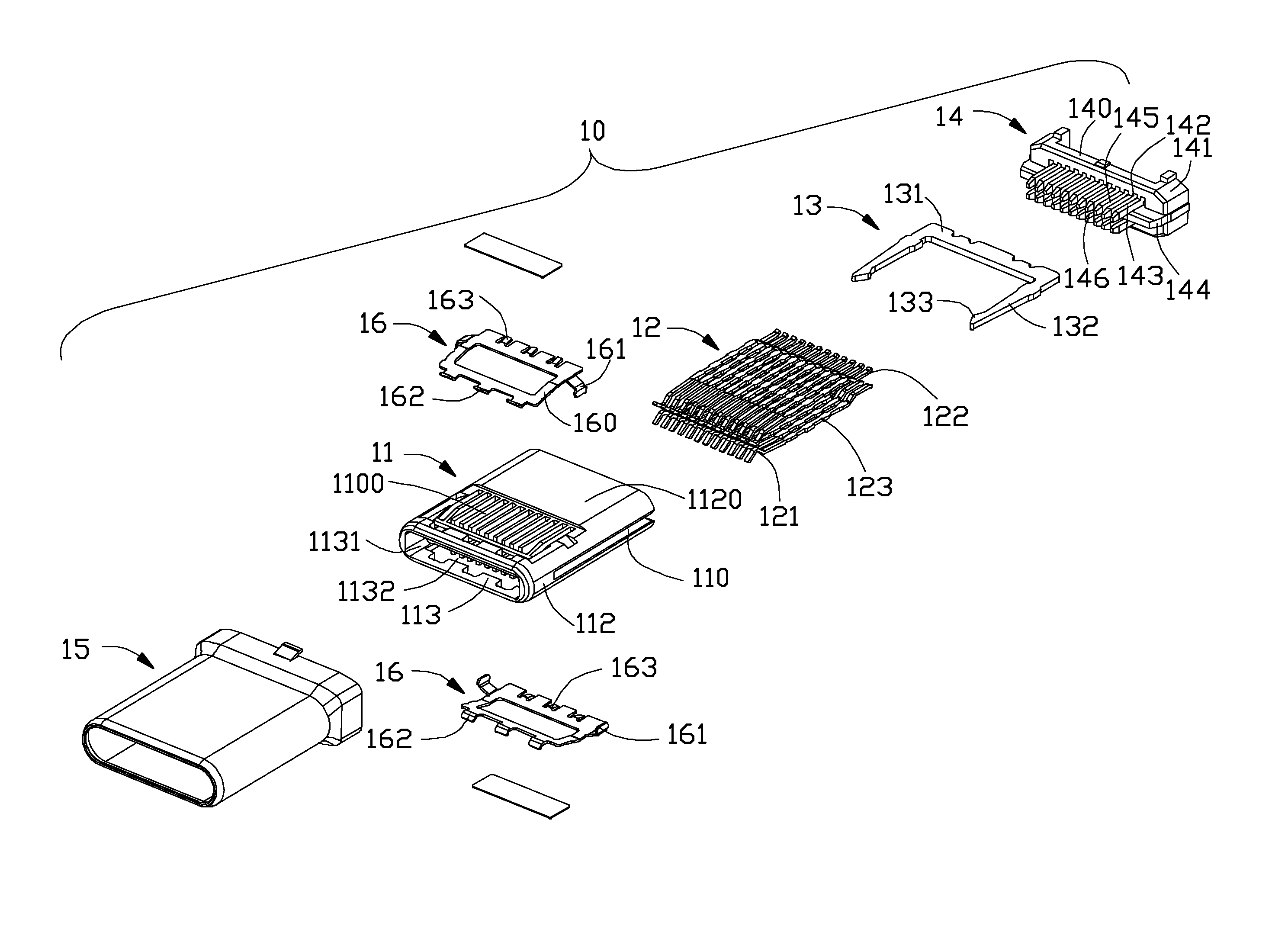
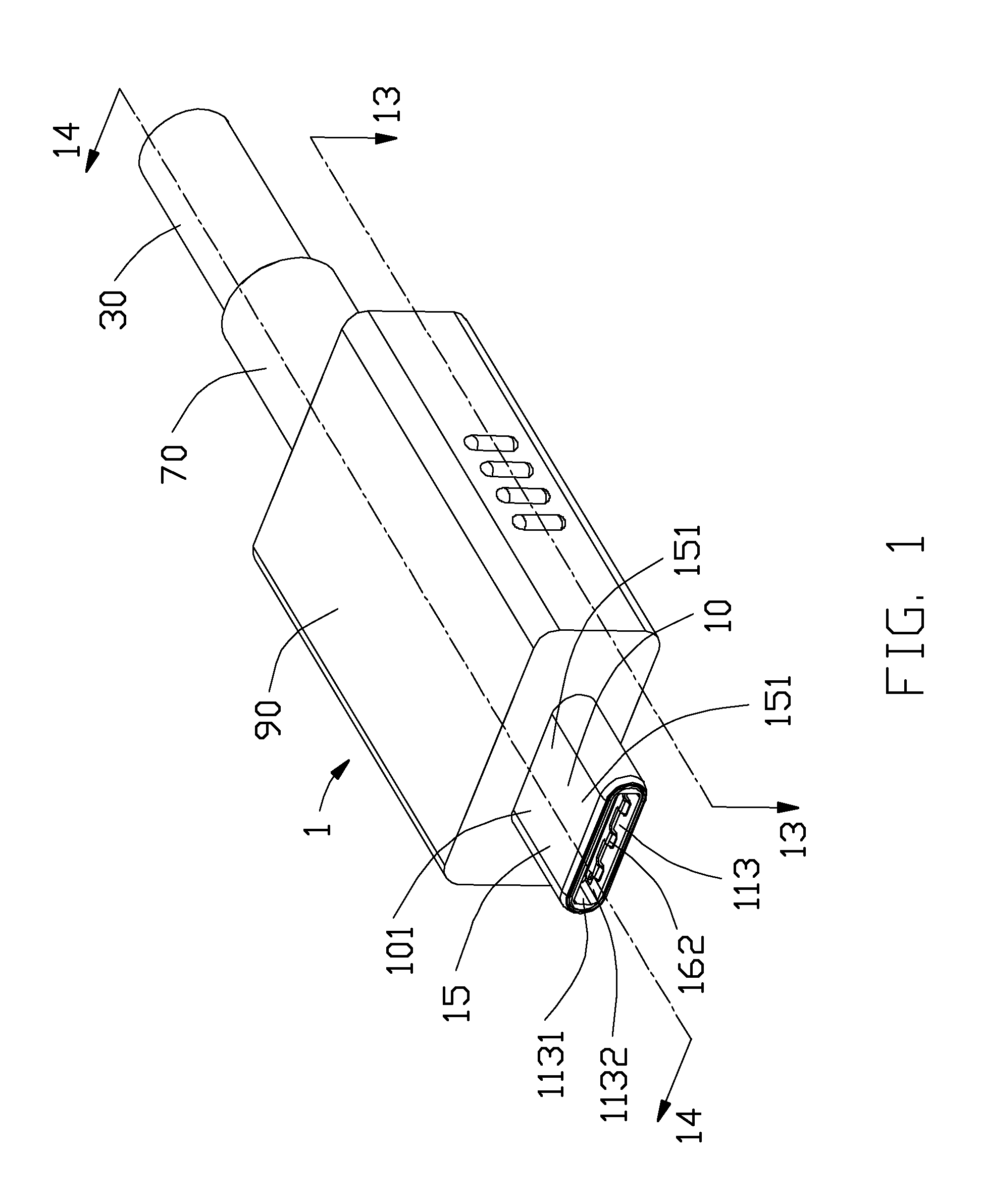
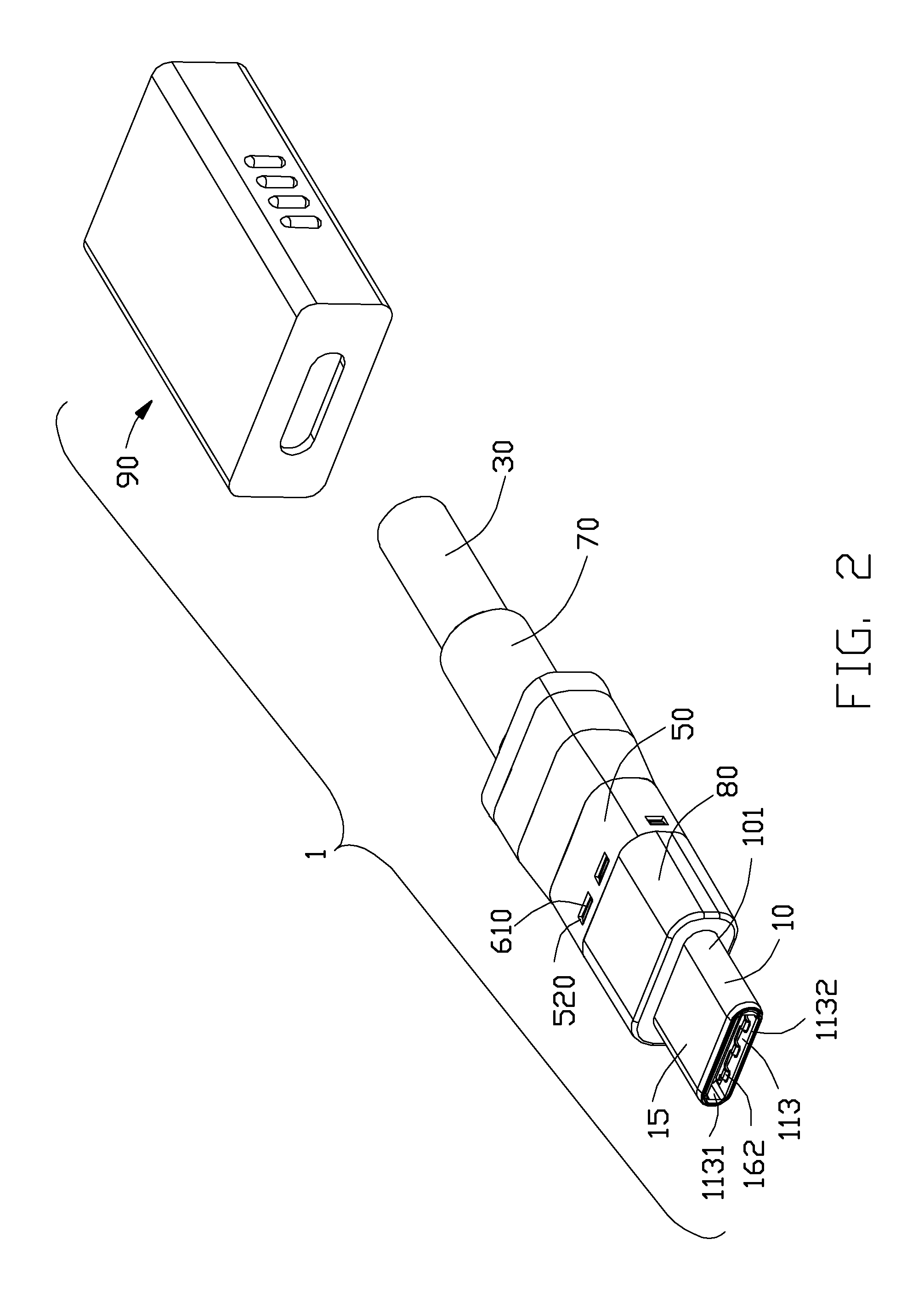
[0036]Referring to FIGS. 1 to 15, an plug connector assembly 1 in accordance with the present invention adapted for mating with a mating connector (Not shown), comprises a mating member 10, a printed circuit board 20 disposed behind and electrically connecting with the mating member 10, a cable 30 comprising a plurality of wires 31 and electrically connected with the printed circuit board 20, a spacer 40 for organizing the wires 31, a first shell 50 having a closed circumference, a second shell 60 having a closed circumference, a strength released member 70, an inner mold 80 molded on the first shell 50, and an outer mold 90. The plug connector assembly can be mated with the mating connected along two opposite directions.

[0037]The mating member 10 has a front mating end 101 for being inserted into the mating connector, and a rear mating end 102 opposite to the front mating end 101. The mating member 10 comprises insulative housing 11, a plurality of first contacts 12 arranged in two...

second embodiment

[0049]Referring to FIGS. 16 to 24, an plug connector assembly 1 in accordance with the present invention adapted for mating with a mating connector (Not shown), comprises mating member 10, a printed circuit board 20 disposed behind and electrically connecting with the mating member 10, a cable 30 comprising a plurality of wires 31 and electrically connected with the printed circuit board 20, a spacer 40 for restricting the wires 31, a first shell 50 having a closed circumference, a second shell 60 having a closed circumference, a strength released member 70, and an outer mold 90. The plug connector assembly can be mated with the mating connected along two opposite directions.

[0050]The mating member 10 of the second embodiment is same as the mating member 10 of the first embodiment, but the latch tabs 1520′ of the third shell 15 of the second embodiment has a little difference compared with the latch tabs 1520 of the third shell 15 of the first embodiment. So, the detailed descriptio...


PUM


Abstract

An plug connector assembly (1) includes a mating member (10) including a front mating end (101) and a rear mating end (102), a cable (30) electrically connected with the mating member, a first shell (50) formed by sheet metal drawing and having a closed circumference, a second shell (60) formed by sheet metal drawing and having a closed circumference. The first shell includes a first front end (51) telescoped with the rear mating end, and a first rear end (52) opposite to the first front end. The second shell (60) includes a second front end (61) telescoped with the first rear end, and a second rear end (62) opposite to the second front end and telescoped on the cable.

Description

BACKGROUND OF THE INVENTION[0001]1. Field of the Invention[0002]The present invention relates to an plug connector assembly connected with a cable, and more particularly to an anti-EMI (electromagnetic interference) structure of the plug connector assembly.[0003]2. Description of Related Arts[0004]U.S. Pat. No. 8,011,968, issued on Sep. 6, 2011 to Lai et al., discloses a plug connector assembly. The plug connector assembly comprises an insulative housing, a plurality of contacts mounted to the insulative housing, a cable electrically connected with the contacts, and a metal shell mounted on an outer side of the insulative housing and cable. The metal shell comprises an upper shell and a bottom shell latched with the upper shell along vertical direction. The bottom shell comprises a front portion having a closed circumference, and a rear portion having an open circumference. The upper shell comprises a body portion having an open circumference to be mated with the rear portion of the...

Claims


Application Information

Patent Timeline
Patent Type & Authority Patents(United States)
IPC IPC(8): H01R13/6593H01R24/60
CPCH01R13/6593H01R24/60
Inventor WU, JERRYCHEN, JUNMENG, FAN-BO
Owner FOXCONN INTERCONNECT TECH LTD
Why Eureka
Try Eureka