Packing element, method to produce it and a column or reactor comprising said element

a technology of packing element and column, applied in the field of packing element, can solve the problems of viscous energy loss, pressure loss accompanying the flow of fluid, disadvantageous increase of pressure loss in the column, etc., and achieve the effect of reducing the number of contact points, minimizing the number of protruding elements, and easy rotation or roll

Active Publication Date: 2016-09-27
SULZER MANAGEMENT AG
View PDF11 Cites 5 Cited by
  • Summary
  • Abstract
  • Description
  • Claims
  • Application Information

AI Technical Summary

Benefits of technology

[0015]The present invention achieves these objects and provides a solution to this problem by means of a shape of the element that is substantially spherical or substantially ellipsoidal, and by means of outer connecting edge elements and outer arched rib elements and optional inner arched rib elements that are embodied such that the total projected area of the packing element when viewed in any direction, preferably a radial direction or axial direction, is partially open due to the presence of an open projected area, wherein it is partially open to an extent that ranges from about 15 to about 50, preferably about 17 to about 40, more preferably about 18 to about 35, most preferably about 20 to about 30%. As a result, the pressure drop fields or the velocity distribution in a packed bed containing these elements will be relatively homogenous, a strong velocity variation will be avoided, a good distribution of the phases will result and local flooding will be minimized. Such elements have relatively homogenous moderate openness in all orientations and thus relatively low and homogenous pressure drop fields in all orientations. Furthermore the substantially spherical or substantially ellipsoidal shape of the packing element contributes to a relatively homogeneous openness of the packing in all of its possible orientations in a bed because of the high rotational symmetry of such shapes. In addition, such relatively rotationally-symmetrical shapes allows the element to be relatively easily and rapidly packed in a random manner into a packed bed by pouring or dumping, and the same shape properties contribute to the elements randomly achieving all possible orientations in the bed, for example, by rolling or rotating during the bed preparation. This high randomness of the relative orientation of the elements and their relatively homogeneous openness and flow and pressure drop properties in all of these various orientations contribute then to more uniform and low local pressure losses and uniform liquid distribution in the bed.
[0029]In an alternative preferred embodiment of the method to produce the packing element, the packing element is made of a thermoplastic material, optionally a thermoplastic material filled with a filler or fibers, in a forming process comprising an injection molding step. Manufacturing the packing element in this way provides a simple and economic production process.

Problems solved by technology

It is noted that increasing the specific surface area of the elements will generally increase the mass transfer efficiency; however, at the same time this increased area will tend to disadvantageously increase the pressure losses in the column.
The pressure losses accompanying the flow of fluids through columns packed with packing elements are caused by simultaneous kinetic and viscous energy losses.
Increasing the pressure loss in the column beyond a particular limit will result in the phenomenon of flooding, in which liquid accumulate becomes entrained in the vapor at the top of the column.
Flooding is detected by sharp increases in column differential pressure, liquid hold-up, and significant decrease in separation efficiency.
However, a very closed projected area in the direction of flow forces the gas phase to take a longer upwards flow path, which contributes then to an increased pressure drop.
One disadvantage of the random packing elements of the prior art is that often the performance of the specific element is highly dependent on its configuration and its orientation with respect to the direction of flow of fluid streams through the element within the packed bed.
In addition, the large surface area in the direction perpendicular to the longitudinal axis of the Pall ring is disadvantageous in that it tends to “shield” or inhibit fluid flow through immediately adjacent rings in the downstream flow direction.
As a result, the use of these packing elements results in irregular pressure drop fields in the packed bed and a poor distribution of the phases.
However the partial torus is not symmetrical around all possible radial axes, and some orientations have quite open projected areas and others are quite closed.
As a result, the use of these packing elements still results in irregular pressure drop fields in the packed bed and a poor distribution of the phases.
This shielding effect can reduce mass transfer efficiency by reducing the element's effective surface area for mass and / or heat transfer.
Furthermore the partial torus form of US '832 A1 does not readily flow into a column or reactor during pouring of a bed, and the irregularly shaped torus may then readily assume a variety of non-equivalent orientations in the bed (e.g. with the longitudinal or radial axis oriented in the vertical direction), thus giving rise to irregular pressure drop fields and a poor distribution of phases in the bed.

Method used


Image

  • Packing element, method to produce it and a column or reactor comprising said element
  • Packing element, method to produce it and a column or reactor comprising said element
  • Packing element, method to produce it and a column or reactor comprising said element

Examples


Embodiment Construction

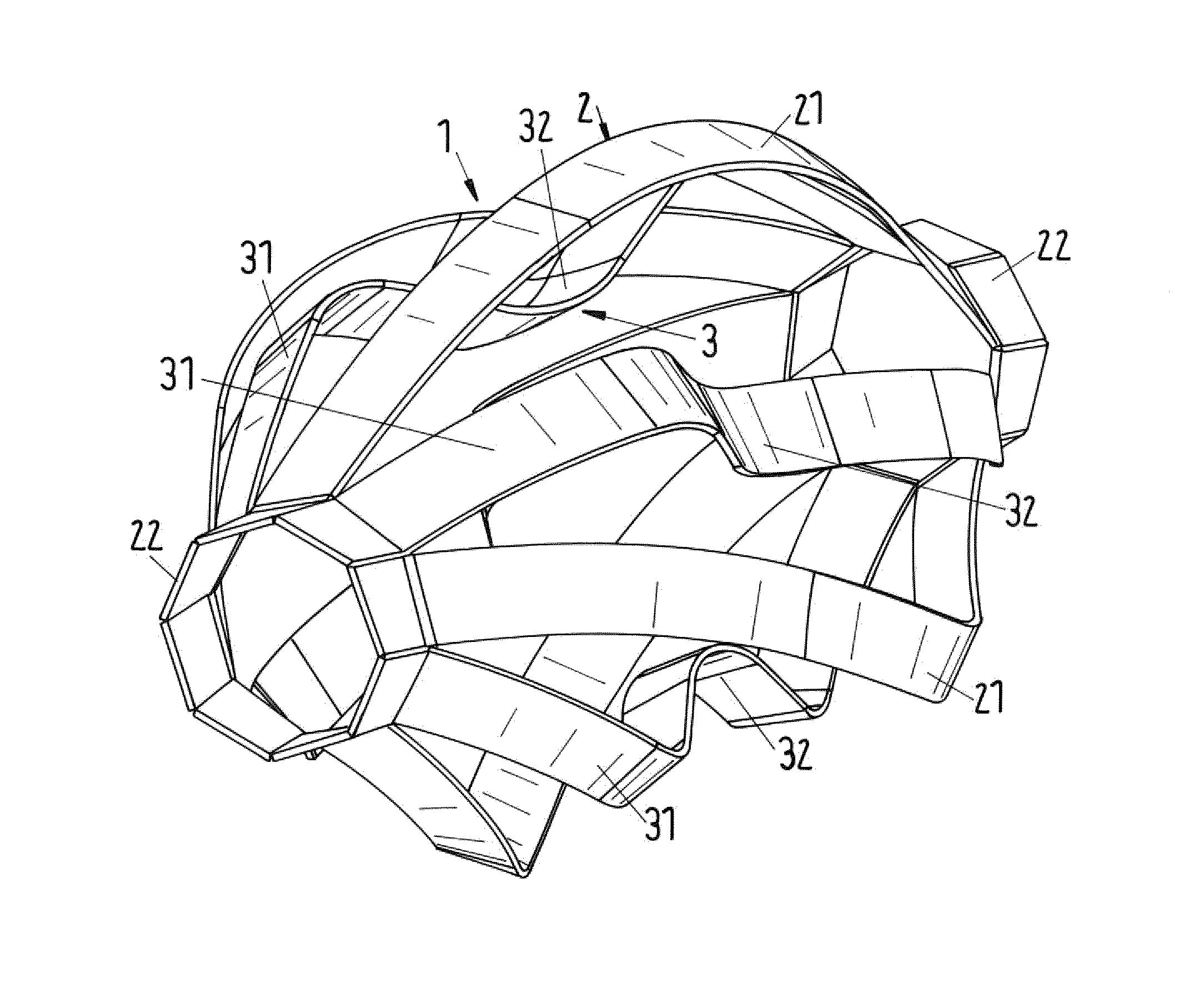
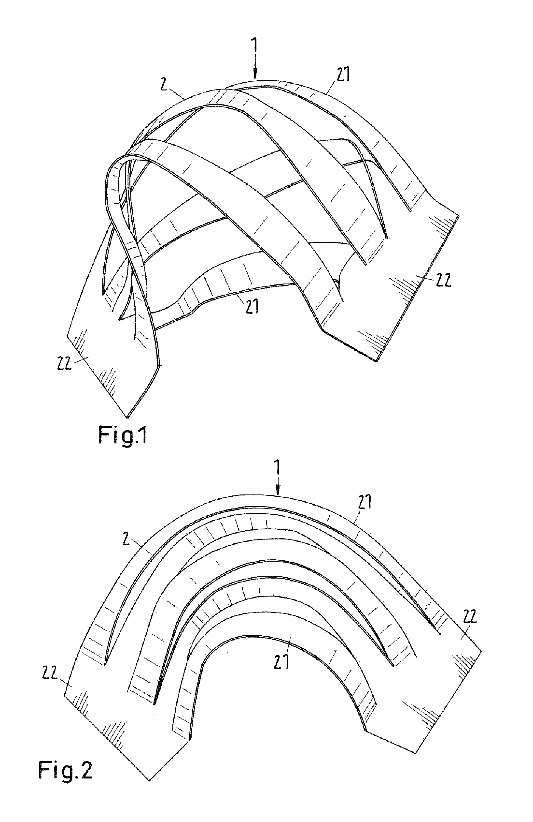
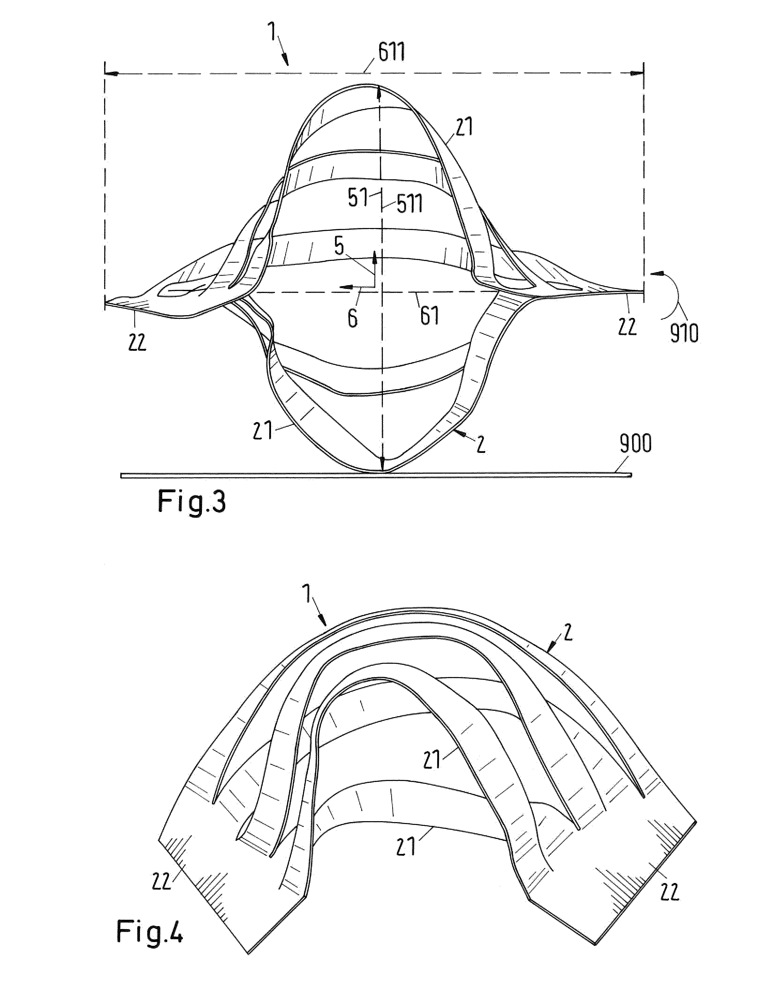
[0050]FIG. 1 shows a schematic view of an embodiment of a packing element according to the invention, which as a whole is labeled with reference number 1. The packing element 1 is not specifically limited as to form, shape, construction or composition unless specifically indicated otherwise, as in the case of the indication of a substantially spherical or substantially ellipsoidal element 1. Any material that can be fabricated can be made into a packing element 1. For reasons of economy and mechanical strength and integrity, packing elements 1 are often made from made of metal, preferably stainless steel or aluminium sheet metal, more preferably of sheet metal made of thickness 3.0 to 0.08 mm, preferably 1.0 to 0.2 mm, or of ceramic, or of a plastic material, preferably a thermoplastic material, optionally a thermoplastic material filled with a filler or fibers, or any other material indicated for the specific application. In one embodiment, the packing element 1 is be made from pol...


PUM

PropertyMeasurementUnit
thicknessaaaaaaaaaa
thicknessaaaaaaaaaa
massaaaaaaaaaa

Abstract

A packing element (1) for use in mass and / or heat transfer processes through which at least one liquid may flow, wherein the packing element (1): has an outer surface (2) comprising three or more outer arched rib elements (21) and two outer connecting edge elements (22), optionally has an inner surface (3) comprising optional inner arched rib elements (31), wherein the element 1 is substantially spherical or substantially ellipsoidal, and wherein the outer connecting edge elements (22) and the outer arched rib elements (21) and optional inner arched rib elements (31) are embodied such that the total projected area (4) of the packing element (1) when viewed in any direction (7), preferably a radial direction (5) or optional axial direction (6), is partially open due to the presence of an open projected area (41), wherein it is open to an extent that ranges from about 15 to about 50, preferably about 17 to about 40, more preferably about 18 to about 35, most preferably about 20 to about 30% of the total projected area (4). The invention further relates to a method for producing said element (1). The present invention further relates also to a column or reactor comprising a bed of said elements (1), a method to prepare said bed, and the use of the element (1) or column or reactor in a mass transfer and / or heat transfer process and / or in a chemical reaction.

Description

BACKGROUND OF THE INVENTION[0001]The present invention relates to a packing element. The present invention also relates to a method to produce said element, the use of said element, and a column or reactor containing a packed bed comprising a plurality of said elements, and a method to produce such packed beds.[0002]Packing elements are known and used for mass transfer and / or heat transfer processes in columns and chemical reactors. For example, random or dumped packing elements are normally employed in gas-liquid or liquid-liquid contact towers or columns to provide mass transfer surfaces between a downwardly flowing fluid, typically a liquid stream, and an upwardly ascending fluid, typically gas or vapor stream or another liquid stream. Random packing elements may be used in a variety of chemical and treatment processes, such as, for example, rectification, stripping, fractionating, absorbing, separating, washing, extraction, or any other chemical, heat exchange, or treatment-type...

Claims


Application Information

Patent Timeline
Patent Type & Authority Patents(United States)
IPC IPC(8): B01F3/04B01J19/30B29C45/00B29L31/18
CPCB01J19/30B01F3/04468B01F3/04496B29C45/00B01J2219/3083B01J2219/30207B01J2219/30211B01J2219/30276B01J2219/30408B01J2219/30416B01J2219/30466B01J2219/30483B01J2219/312B01J2219/318B01J2219/3183B29L2031/18Y10T29/49B01F23/2321B01F23/2322
Inventor AUSNER, ILJAKEHRER, FLORIAN
Owner SULZER MANAGEMENT AG
Why Eureka
Try Eureka