Method and device for layered buildup of a shaped element

a technology of layered buildup and shaped elements, which is applied in the direction of additive manufacturing processes, applications, manufacturing tools, etc., can solve the problems of high cost of producing such shaped elements, high cost of producing negative molds, and high cost of suitable materials

Active Publication Date: 2016-10-04
SCHWARZLER KLAUS
View PDF16 Cites 70 Cited by
  • Summary
  • Abstract
  • Description
  • Claims
  • Application Information

AI Technical Summary

Benefits of technology

[0015]In case this is not yet the case, a second option is to let a support material contact the defining surfaces of the shaped element while it is being built up, thus during its curing time, wherein the support material for example prevents an undesirable deformation of the not yet cured layers.
[0056]Independently from the type of buildup method, the device can include one or plural reinforcement dispensers. In flexible reinforcements like strands or fabric bands made from plastic material, glass, carbon or similar flexible materials, these can be kept wound on a storage roller in a simple manner, wherein they are increasingly wound off from the storage roller. These reinforcements can be placed in the plane of the respective buildup layer, parallel and also perpendicular to the main plane of the layer or they can also extend through all layers with their main extension perpendicular to the layer plane with increasing layer buildup.

Problems solved by technology

The complexity for producing a negative mold, however, only pays off when this negative mold is used several times, most advantageously used very many times. Accordingly, producing such shaped elements was expensive since they were produced in small numbers or even as one-offs since no other production method was feasible.
Furthermore, suitable materials are expensive so that they are not suited for producing large volume components which in particular must not be excessively expensive.
However, there is a whole series of shaped elements which have to be produced at a low price and at a large volume and for which this method was not suitable so far, for example finished components made from concrete, casting molds for metal casting, fiber reinforced plastic materials for custom vehicle construction, in particular marine construction or car body construction and many other applications.

Method used


Image

  • Method and device for layered buildup of a shaped element
  • Method and device for layered buildup of a shaped element
  • Method and device for layered buildup of a shaped element

Examples


first embodiment

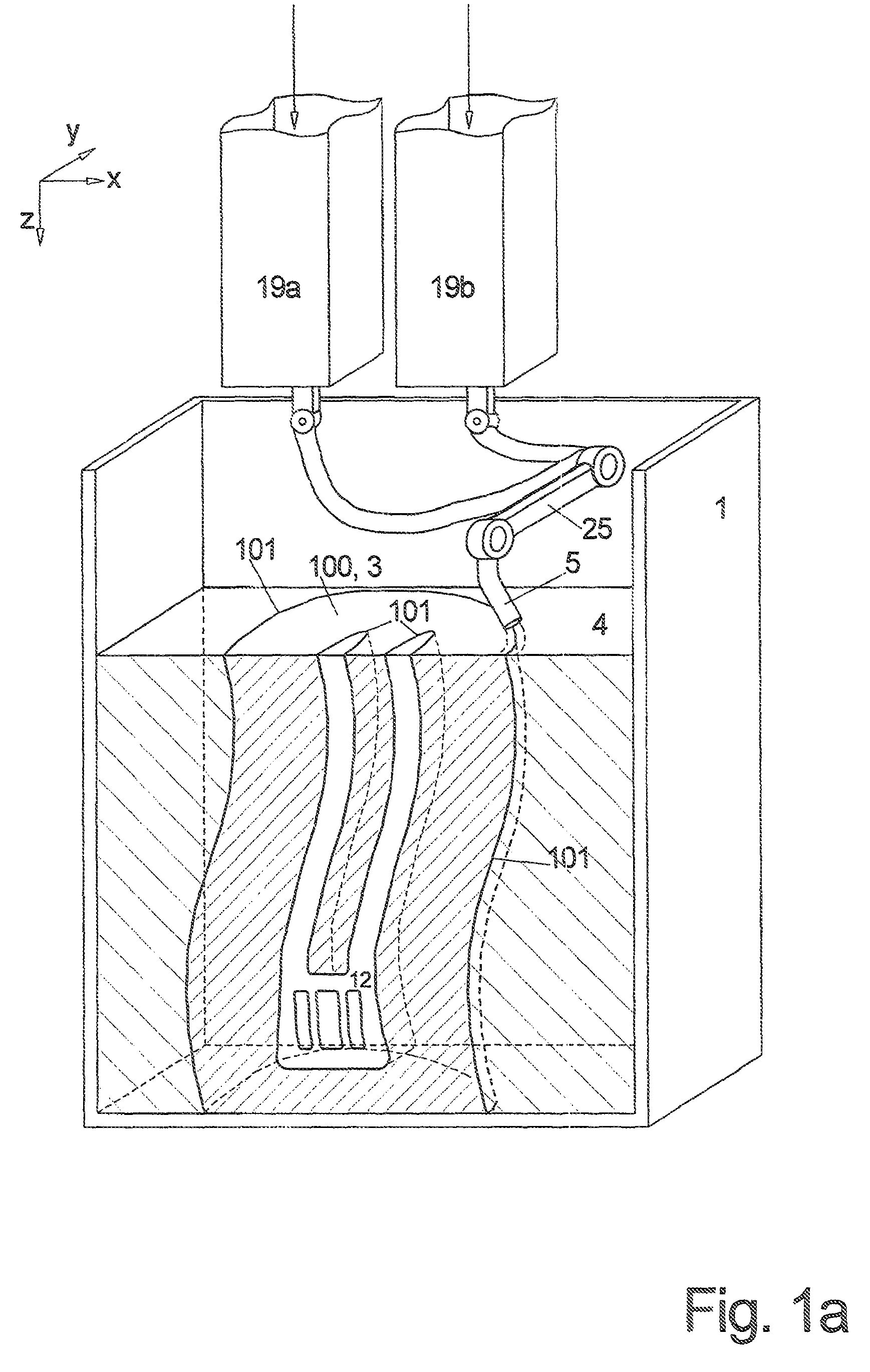
[0062]FIG. 1a illustrates the invention;

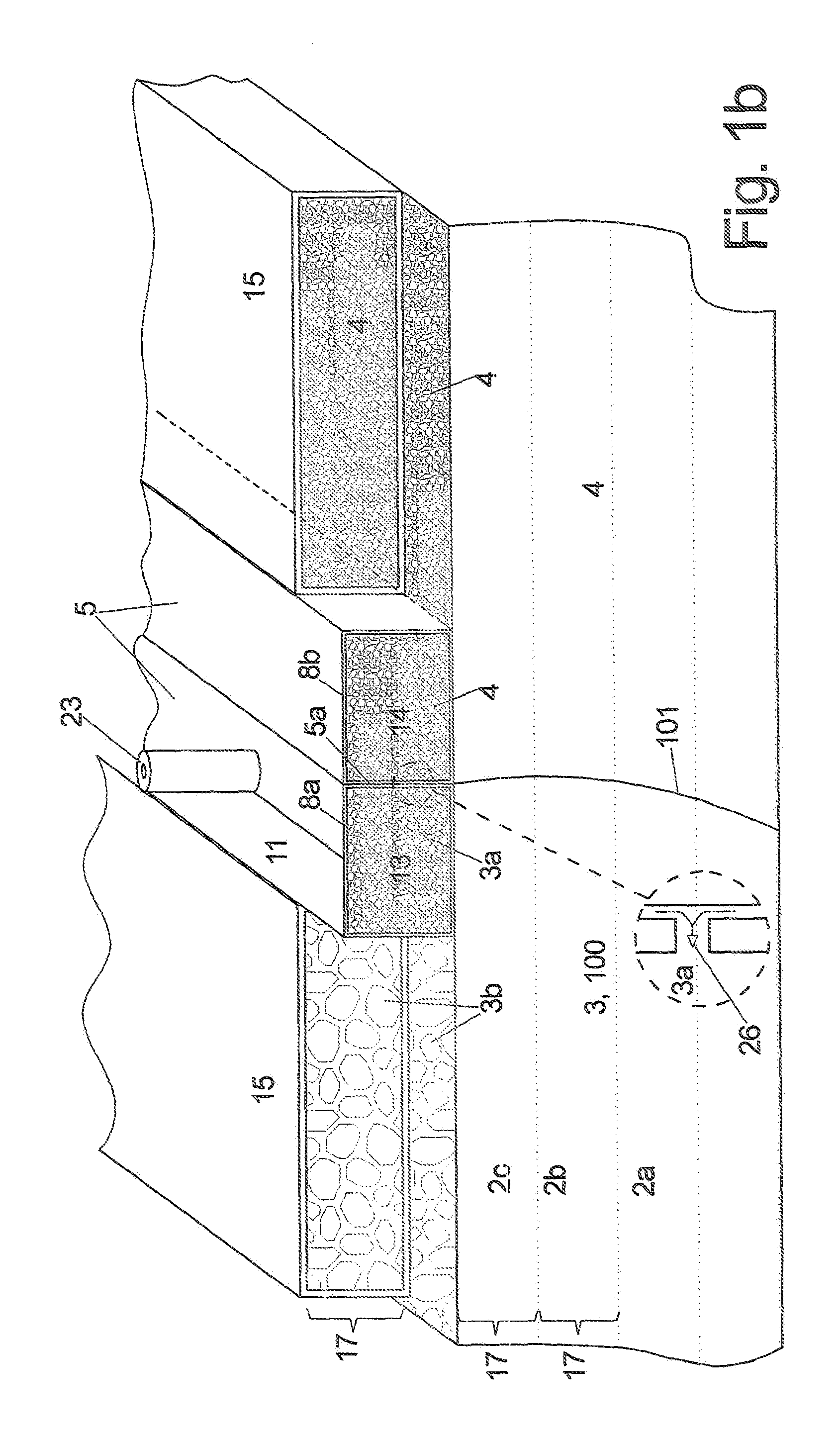
[0063]FIG. 1b illustrates a detail sectional view of FIG. 1a;

[0064]FIG. 1c, d illustrate details of FIG. 1a in top view;

second embodiment

[0065]FIG. 2a illustrates a second embodiment according to the invention;

[0066]FIG. 2b illustrates a detail sectional view of FIG. 2a; and

[0067]FIG. 2c illustrates a detail top view of FIG. 2a

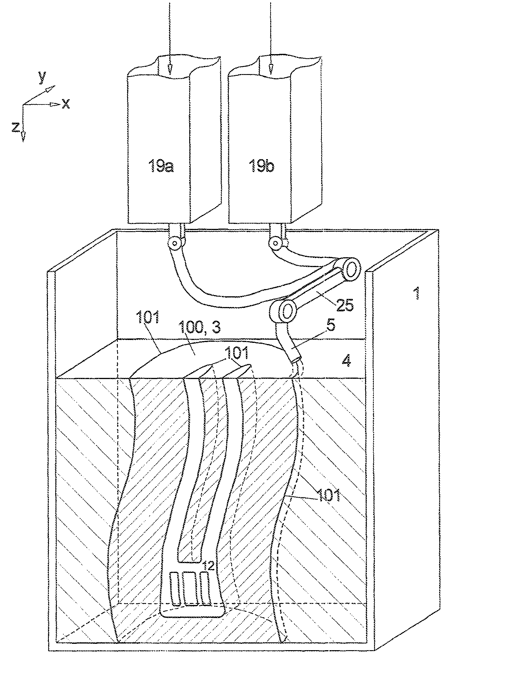
[0068]FIG. 1a illustrates the device for the first method according to the invention in a vertical sectional view.

[0069]Thus, a shaped element 100 is built up in an open container 1 from bottom to top, thus starting at the base of the container 1 from layers 2a, b, c horizontally arranged on top of one another in that element material 3 is applied in layers for forming the desired shaped element 100 and also by applying support material 4 from at least one nozzle 5 about the shaped element 100, wherein the nozzle 5 is movable in a controlled manner about the horizontal surface in an interior of the container 1 and is connected with storage containers 19a, b from which materials 3 and 4 are supplied which exit from the nozzle 5.

[0070]An enlarged representation in a vertical sectional view is pr...


PUM

PropertyMeasurementUnit
thicknessesaaaaaaaaaa
heightaaaaaaaaaa
thicknessesaaaaaaaaaa

Abstract

Since concrete materials do not cure quick enough when prototyping methods are used, so that a lower layer (2a) is already completely cured when the next layer (2b) is applied, a support material (4) is applied about the formed element (100) that is being built up in order to compensate for the lack of pressure resistance of the lower layer (2a), wherein the support material preferably has the same specific weight as the material (3) of the formed element (100). Thus, 3D-printing as well as selective curing are facilitated as build up methods.

Description

I. FIELD OF THE INVENTION[0001]The invention relates to a method for a layered buildup of a shaped element from curing material and to a device for the method.II. TECHNICAL BACKGROUND[0002]In the past when a shaped elements from a curing material were to be produced, initially a respective negative mold had to be produced into which the typically liquid base material was introduced and in which it could cure.[0003]The complexity for producing a negative mold, however, only pays off when this negative mold is used several times, most advantageously used very many times. Accordingly, producing such shaped elements was expensive since they were produced in small numbers or even as one-offs since no other production method was feasible.[0004]For a couple of years, however, production without negative mold is feasible through so-called prototyping, however, only with particular plastic materials as base materials and only with limited dimensions up to for example 1 m3. There are two diff...

Claims


Application Information

Patent Timeline
Patent Type & Authority Patents(United States)
IPC IPC(8): B29C67/00B33Y10/00B33Y40/00
CPCB29C67/0055B29C67/0059B29C67/0081B29C67/0092B29C67/0051B29C67/0066B29K2995/0021B33Y10/00B33Y40/00B29C64/112B29C64/135B29C64/165B29C64/40B33Y30/00
Inventor SCHWARZLER, KLAUS
Owner SCHWARZLER KLAUS
Why Eureka
Try Eureka