
Floating type self-lifting drilling platform

a drilling platform and floating technology, applied in floating buildings, special-purpose vessels, transportation and packaging, etc., can solve the problems of complex operation during positioning or dislocation of the drilling platform, increased cost, and sensitive to wave waves, so as to increase the depth and range of operation sea area, improve the stability, and improve the effect of movement performan

Active Publication Date: 2016-10-04
SHENZHEN GRADUATE SCHOOL TSINGHUA UNIV
View PDF13 Cites 0 Cited by
  • Summary
  • Abstract
  • Description
  • Claims
  • Application Information

AI Technical Summary

Benefits of technology

The patent describes a new type of mobile drilling platform that can be used in water depths up to 500 meters. This platform is made up of a floating cushion and pile legs that provide buoyancy and stability. Compared to traditional platforms, it has a larger buoyancy force and greater depth of operation. It can be easily towed and has good stability during operation and can store more oil. The platform also has a large oil storage capacity. Overall, this new platform offers improved efficiency and flexibility for offshore drilling and exploration.

Problems solved by technology

However, the operation during positioning or dislocation of the platform is complicated, and the platform is sensitive to the wave.
Moreover, as the water depth is increased, the cost is increased significantly.
If a semi-submersible type drilling platform and a drilling ship are newly built for a new oil production region with the water depth of 200 to 500 meters, requirements on exploration technologies and constructions may be met, but the cost is huge, it may be overkill, and has a poor economical efficiency.
On the other hand, the number of existing self-lifting type drilling platforms is large, but a lot of the platforms in service cannot be continuously used due to the service lives of pile legs and pile shoes, and there will be a large number of self-lifting type drilling platforms retire in future ten years.

Method used


Image

  • Floating type self-lifting drilling platform
  • Floating type self-lifting drilling platform
  • Floating type self-lifting drilling platform

Examples


Embodiment Construction

[0037]In order to make objectives, technical solutions and advantages of embodiments of the present application more clearly, the technical solutions in the preferred embodiments of the present application are described clearly and completely in the following through the accompanying drawings.

[0038]A floating type self-lifting drilling platform (briefly referred to as a platform) of the present application may be merely used for drilling, merely used for production, or may be used for drilling and production at the same time. The present application being used for drilling and production at the same time is used as an example for illustration in the following.

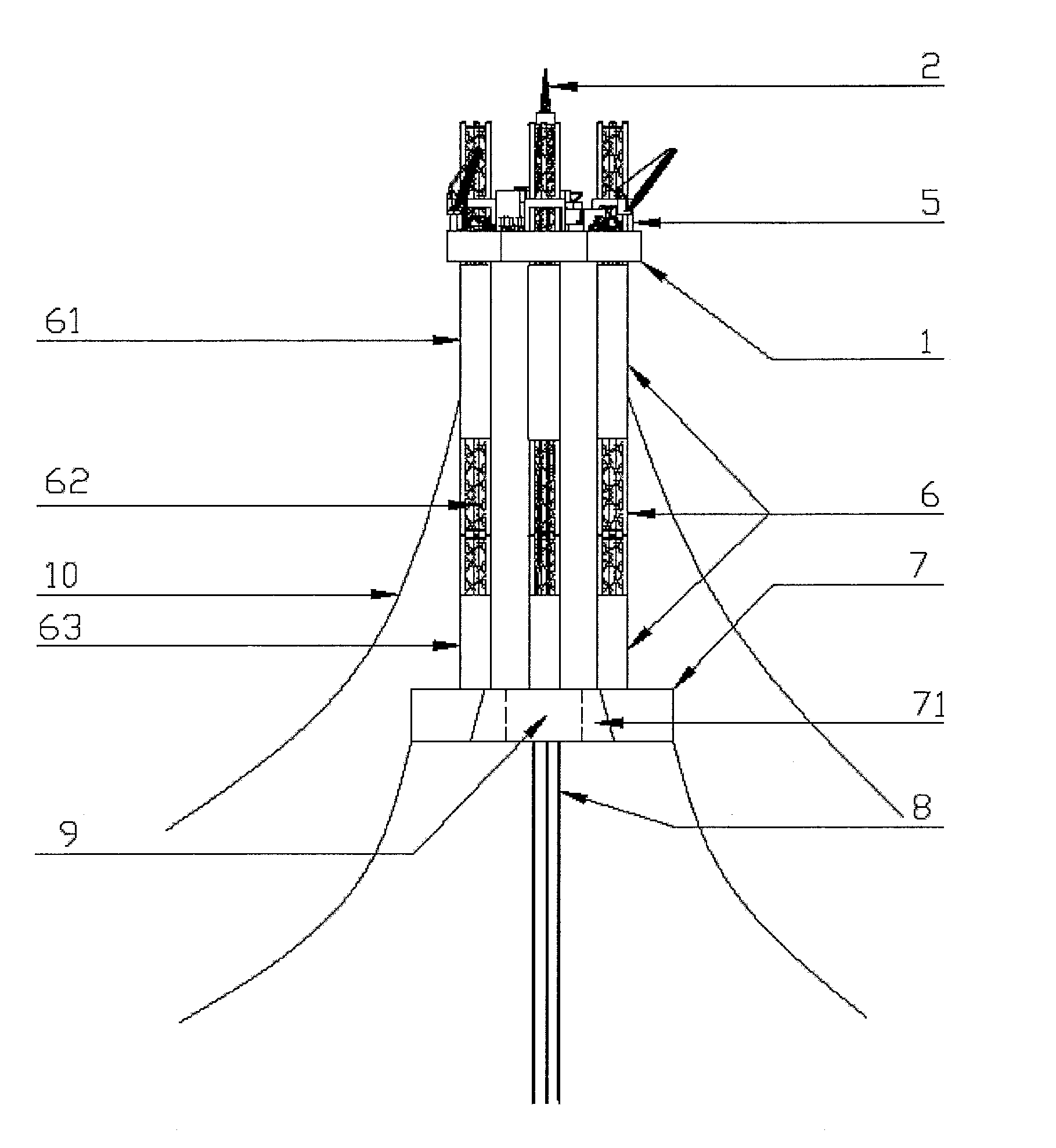
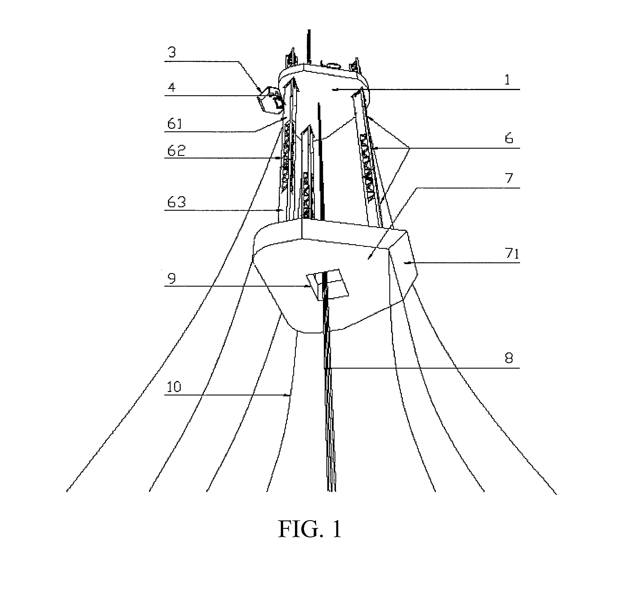
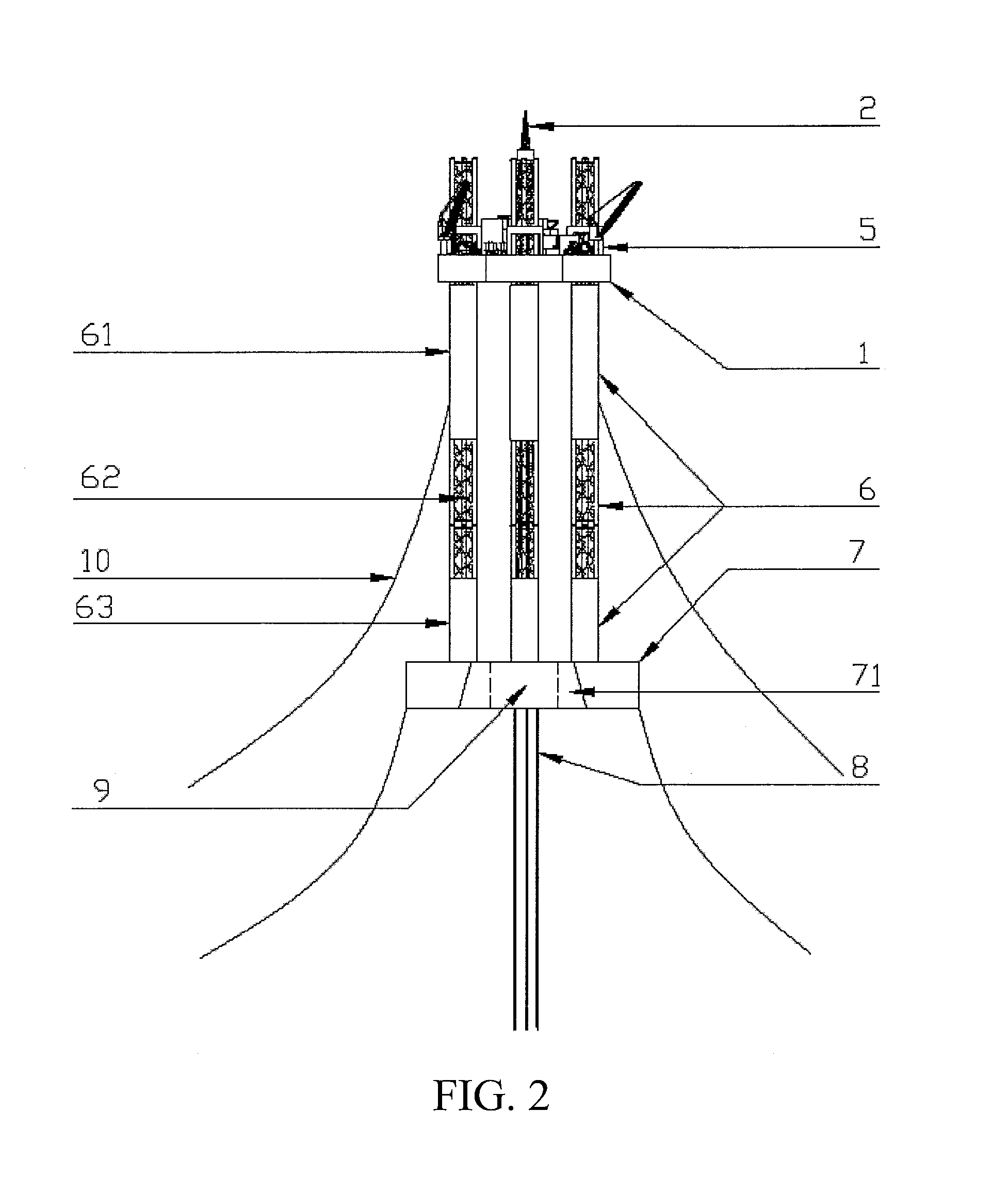
[0039]As shown in FIG. 1 to FIG. 4, in a preferred embodiment, the platform includes: a main deck 1 and an upper structure thereof, a floating cushion 7, pile legs 6, a mooring system, a lifting mechanism 5, and a propeller 4, where the upper structure on the main deck 1 may include modules such as a drilling module, a producti...


PUM


Abstract

A floating type self-lifting drilling platform includes a main deck, a floating cushion, pile legs, a lifting mechanism and a mooring system. The area and thickness of the floating cushionare both greater than those of the main deck, the middle part is provided with a moon pool, and the inner part is partitioned into multiple cabins; there are three pile legs, the pile legs are truss structures, the bottom part of each of the pile legs is rigidly connected with the floating cushion, and the main deck lifts vertically along the pile legs through the lifting mechanism and is fixed at a preset height; each pile leg includes upper and lower hollow sealing bodies; the water line is located in the height range of the upper section during the operation and positioned through the mooring system.

Description

BACKGROUND[0001]1. Technical Field[0002]The present application relates to offshore oil and gas drilling devices, and in particular, to a floating type self-lifting drilling platform.[0003]2. Related Art[0004]In the current trend of increasing energy demands in the world and gradually running out onshore oil and gas resources, exploring broader energy supply ways has become a key point of development all over the world. The offshore oil and gas exploration technology is developed especially rapid. The proportion of the total yield of the offshore oil and gas in the total yield of the oil and gas in the world has increased from 20% in 1997 to more than 40% in nowadays, where the yield of deep water oil and gas accounts for about more than 30% of the yield of the offshore oil and gas. Therefore, for three offshore drilling devices, including a self-lifting type drilling platform, a semi-submersible type drilling platform and a drilling ship, operation in deepwater is a main developmen...

Claims


Application Information

Patent Timeline
Patent Type & Authority Patents(United States)
IPC IPC(8): E02B17/02B63B35/44E21B7/128
CPCB63B35/4413B63B35/44E21B7/128B63B2035/448B63B2001/044
Inventor ZHENG, XIANGYUANCHEN, DAOYIYU, HAN
Owner SHENZHEN GRADUATE SCHOOL TSINGHUA UNIV
Learn More